P341/EN AD/F43 Update Documentation
(AD) -30
MiCOM P341
The Phase Sequence setting applies to a power system that has a permanent phase
sequence of either ABC or ACB. It is also applicable for temporary phase reversal which
affects all the VTs and CTs. As distinct from the other phase reversal settings, this setting
does not perform any internal phase swapping of the analogue channels.
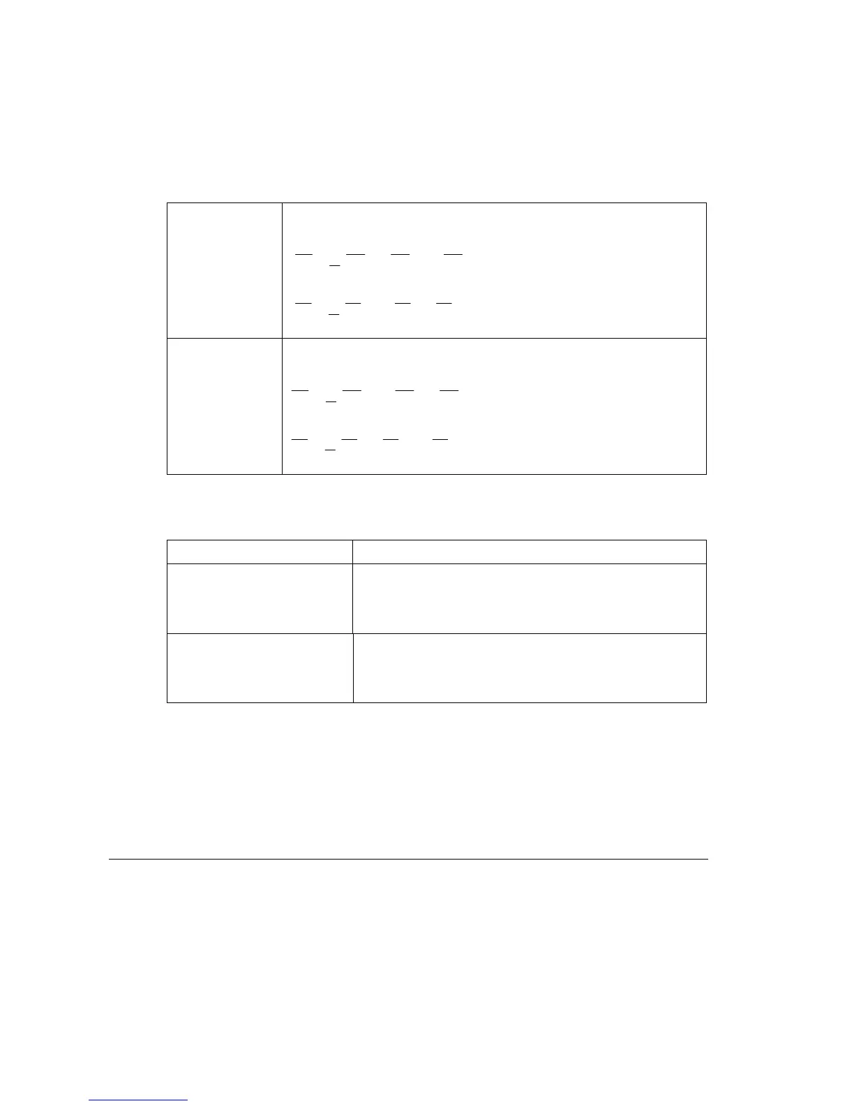
The Phase Sequence setting affects the sequence component calculations as follows:
Standard ABC The calculations of positive (I
1
, V
1
) and negative (I
2
, V
2
) phase
sequence voltage and current remain unchanged as follows:
c
2
ba1
XXX
3
1
X
cb
2
a2 XXX
3
1
X
Reverse ACB The calculations of positive (I
1
, V
1
) and negative (I
2
, V
2
) phase
sequence voltage and current are given by the equations:
cb
2
a1
XXX
3
1
X
c
2
ba2 XXX
3
1
X
Where:
1201
The Phase Sequence setting also affects the directional overcurrent protection as follows:
Phase Rotation 67 (Directional Overcurrent)
Standard ABC Phase A use Ia, Vbc
Phase B use Ib, Vca
Phase C use Ic, Vab
Reverse ACB Phase A use Ia, -Vbc
Phase B use Ib, -Vca
Phase C use Ic, -Vab
The VT Reversal and CT1 Reversal settings apply to applications where some or all of the
voltage or current inputs are temporarily reversed, as in pump storage applications. The
settings affect the order of the analogue channels in the relay and are set to emulate the
order of the channels on the power system. So, assuming the settings emulate the change
in phase configuration on the power system all the protection functions will naturally operate
as per a standard phase rotation system. The phase sequence calculations and the
protection functions all remain unchanged.
4.9 Disturbance recorder
The integral disturbance recorder has an area of memory specifically set aside for record
storage. The number of records that may be stored by the relay is dependent upon the
selected recording duration. The relay can typically store a minimum of 50 records, each of
1.5 seconds duration (8 analog channels and 32 digital channels). VDEW relays, however,
have the same total record length but the VDEW protocol dictates that only 8 records (of 3
seconds duration) can be extracted via the rear port. Disturbance records continue to be
recorded until the available memory is exhausted, at which time the oldest record(s) are
overwritten to make space for the newest one.