Update Documentation P341/EN AD/F43
MiCOM P341
(AD) -43
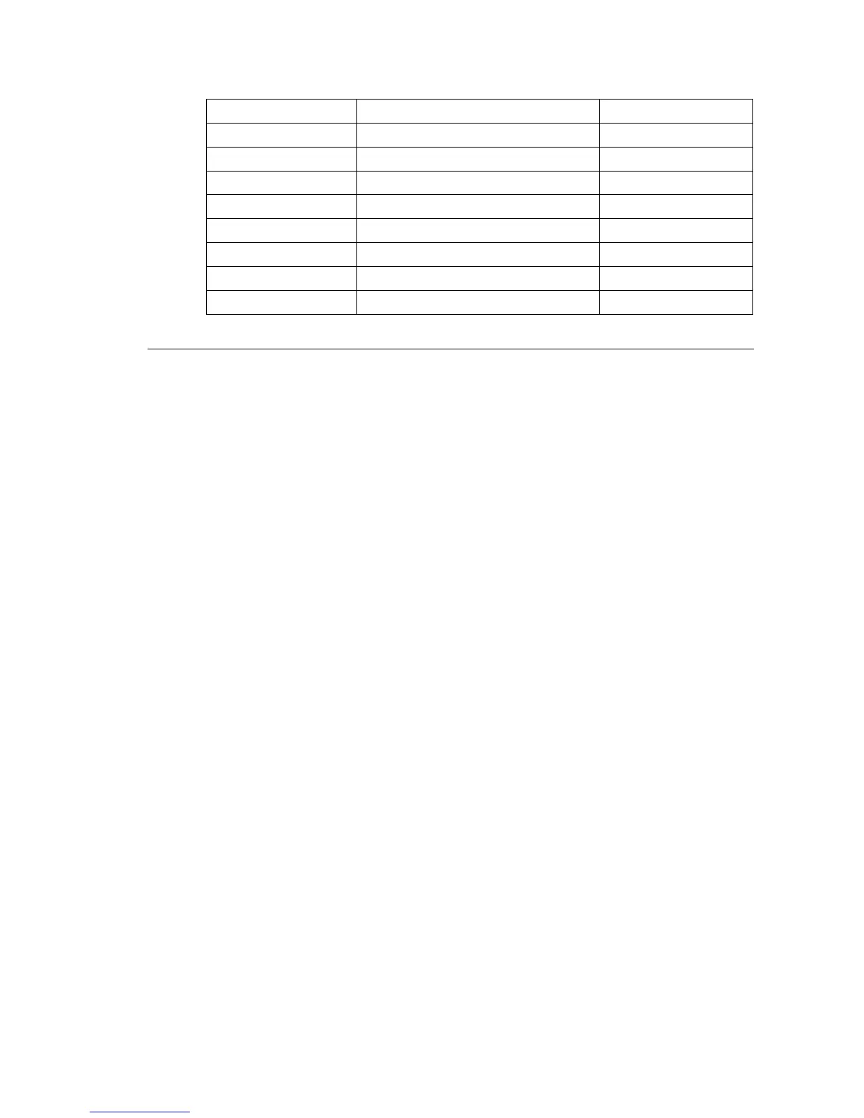
Pin Signal Name Signal Definition
1 TXP Transmit (positive)
2 TXN Transmit (negative)
3 RXP Receive (positive)
4 - Not used
5 - Not used
6 RXN Receive (negative)
7 - Not used
8 - Not used
Table 4: Signals on the Ethernet connector
RELAY DESCRIPTION (P341/EN HW/F33)
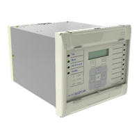
1.1.6. Ethernet board
This is a mandatory board for IEC 61850 enabled relays. It provides network connectivity
through either copper or fiber media at rates of 10Mb/s (copper only) or 100Mb/s. There is
also an option on this board to specify IRIG-B port (modulated or un-modulated). This board,
the IRIG-B board and second rear comms board are mutually exclusive as they all utilize slot
A within the relay case.
All modules are connected by a parallel data and address bus which allows the processor
board to send and receive information to and from the other modules as required.
There is also a separate serial data bus for conveying sample data from the input module to
the processor. Figure 1 shows the modules of the relay and the flow of information between
them.