5
©2020 Micro-Air, Inc. July 22, 2020 Revision 1.07
5. Insert the thermostat mounting pins into the back of the thermostat in the provided holes while
pressing it against the wall. Press down gently with the thermostat flush against the wall to lock down
the thermostat.
Multi-Zone OEM (ASY-350)
Includes Dometic™ Multi-zone CCC2 systems only
1. Press up on the tab located on the bottom of the original Dometic™ thermostat with a small
screw driver and tilt the base of the display toward you to remove the thermostat faceplate.
2. Remove the four mounting screws from the thermostat.
3. Unplug the original thermostat from the cable. Press the small tab toward the cable and gently
pull out the connector.
4. Use the mounting template to locate and drill two 3/16” (4.76mm) holes. Insert the wall anchors
into the holes. Place the plastic mounting bracket against the wall with the smaller side closest
to the wall. Screw the wall mounting bracket into the wall anchors using the provided screws.
Remove the center plastic spacer after the screws are tight.
5. Plug the thermostat cable into the EasyTouch RV thermostat.
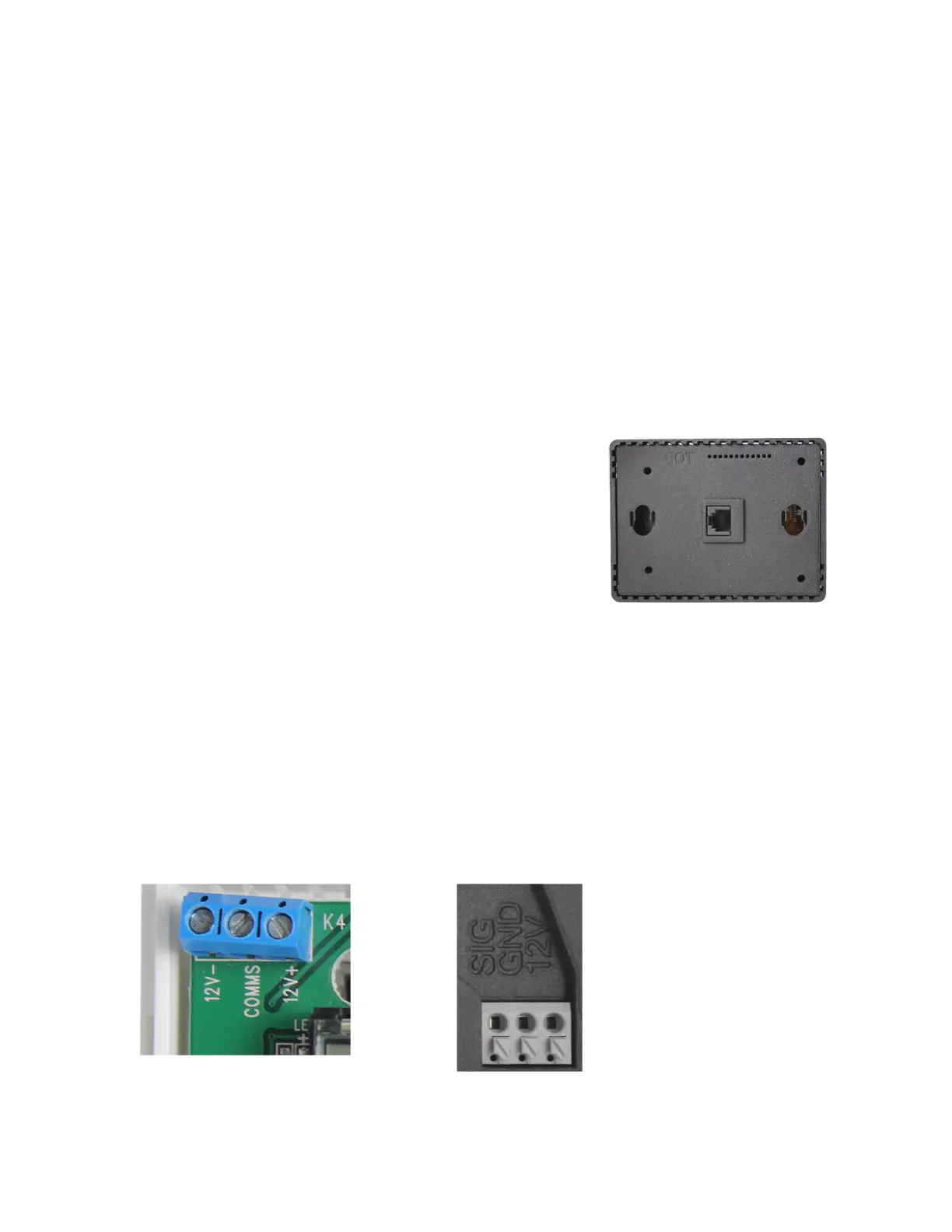
6. Insert the thermostat mounting pins into the back of the
thermostat in the provided holes while pressing it against the
wall. Press down gently with the thermostat flush against the
wall to lock down the thermostat.
Single-Zone OEM (ASY-351)
Includes Dometic™ Single zone systems only
1. Press up on the tab located on the bottom of the original Dometic™ thermostat with a small
screw driver and tilt the base of the display toward you to remove the thermostat faceplate.
2. Take a picture of the three wires connected inside the thermostat. Disconnect the three wires.
3. Remove the four mounting screws from the thermostat and completely remove the thermostat.
4. Use the mounting template to locate and drill two 3/16” (4.76mm) holes. Insert the wall anchors
into the holes. Place the plastic mounting bracket against the wall with the smaller side closest
to the wall. Screw the wall mounting bracket into the wall anchors using the provided screws.
Remove the center plastic spacer after the screws are tight.
5. Connect 12V- to GND, COMMS to SIG, and 12V+ to 12V from the previously disconnected wires.