dsPIC33/PIC24 Family Reference Manual
DS30009740B-page 2 2010-2013 Microchip Technology Inc.
1.0 INTRODUCTION
The Liquid Crystal Display (LCD) driver module generates the timing control to drive a Static or
Multiplexed LCD panel. In the 100-pin devices (PIC24FJXXXGA3XX), the module drives panels
of up to eight commons and up to 60 segments when 5 to 8 commons are used, and up to
64 segments when 1 to 4 commons are used. It also provides control of the LCD pixel data.
The LCD driver module supports:
• Direct driving of LCD panel
• Three LCD clock sources with selectable prescaler
• Up to eight commons:
- Static (one common)
- 1/2 Multiplex (two commons)
- 1/3 Multiplex (three commons)
- 1/8 Multiplex (eight commons)
• Up to 60 segments (in 100-pin devices when 1/5-1/8 Multiplex is selected), 64 (in 100-pin
devices when up to 1/4 Multiplex is selected), 46 (in 80-pin devices when 1/5-1/8 Multiplex
is selected), 50 (in 80-pin devices when up to 1/4 Multiplex is selected), 30 (in 64-pin
devices when 1/5-1/8 Multiplex is selected) and 34 (in 64-pin devices when up to
1/4 Multiplex is selected)
• Static, 1/2 or 1/3 LCD Bias
• On-chip Bias generator with dedicated charge pump to support a range of fixed and
variable Bias options
• Internal resistors for Bias voltage generation
• Software contrast control for LCD using the internal biasing
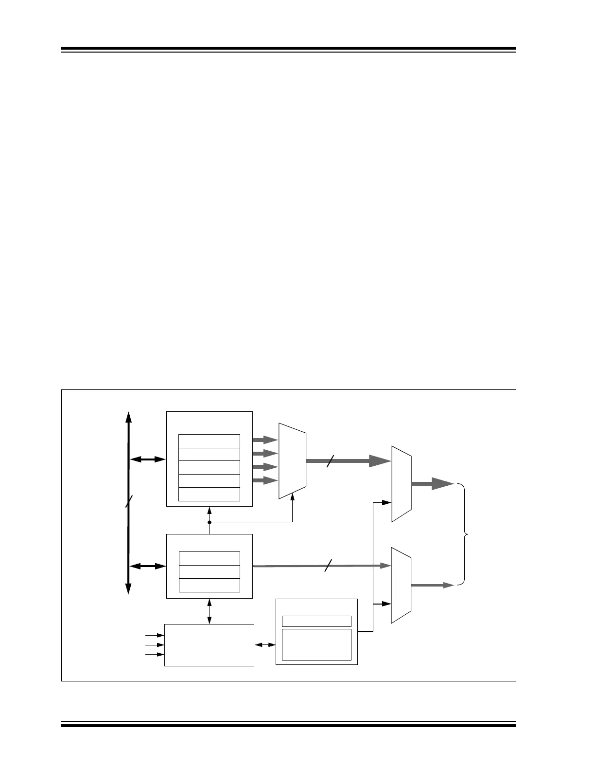
A simplified block diagram of the module is shown in Figure 1-1.
Figure 1-1: LCD Driver Module Block Diagram
COM<7:0>
Timing Control
Data Bus
SOSC
FRC Oscillator
LPRC Oscillator
512
to
64
MUX
SEG<63:0>
To I/O Pins
32 x 16 (= 8x 64)
LCD DATA
LCDCON
LCDPS
LCDSEx
LCDDATA0
LCDDATA1
LCDDATA30
LCDDATA31
.
.
.
LCD Bias Generation
LCD Clock
Source Select
LCD
Charge Pump
64
8
Bias
Voltage
16
(Secondary Oscillator)
Resistor Ladder