Configuration
2016 Microchip Technology Inc. DS50002449A-page 21
2.10 STATUS INDICATOR LEDS
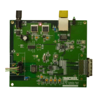
The board includes the following LEDs:
• D2: KSZ8061 3.3V power indicator LED (red). Note that the KSZ8061 and
KSZ8081 have separate voltage regulators, and that there is no equivalent power
LED for the KSZ8081.
• D3: KSZ8061 SIGD (signal detect) LED (green). SIGD is also accessible at J7 pin 8.
• D4: KSZ8061 RXER (RX error) latch LED (red). RXER is an MII output signal from
the KSZ8061. If RXER ever goes high, that state is captured and held by latch
(U7). This latch is reset by the press button S3.
• D7: KSZ8081 link status LEDs (green). These are standard link/activity and speed
status LEDs. There are no equivalent link status LEDs for the KSZ8061.
FIGURE 2-8: LOCATION OF LEDS AND RESET BUTTONS
2.11 RESET BUTTONS
The board has three push buttons, which are all used for reset purposes:
• S1: Chip reset for KSZ8061 (U1)
• S2: Chip reset for KSZ8081 (U2)
• S3: KSZ8061 RXER latch reset (U7, D4)

 Loading...