IBEX 8 Nozzle SMALL FRAME_June 2020 June 20 Page 7 of 41
3. INSTALLATION OF THE PUMP MODULE
Installation Procedure:
• Determine pump module location
• Identify water supply/connection for the system
• Determine routing of the high pressure manifold from the pump.
• Establish drainage location from the pump.
• Verify correct electrical power supply to the pump.
• Determine all of the above for optional Equipment - Zone Controllers, Temperature/Humidity Controllers, Reverse
Osmosis, UV sterilizers, etc...
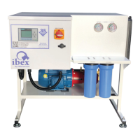
POSITIONING THE PUMP MODULE
The pump module requires a flat level surface. Position selection will largely depend on
the availability of power and water, but remember the points outlined on the previous
pages as the terms of the pump warranty depend upon it.
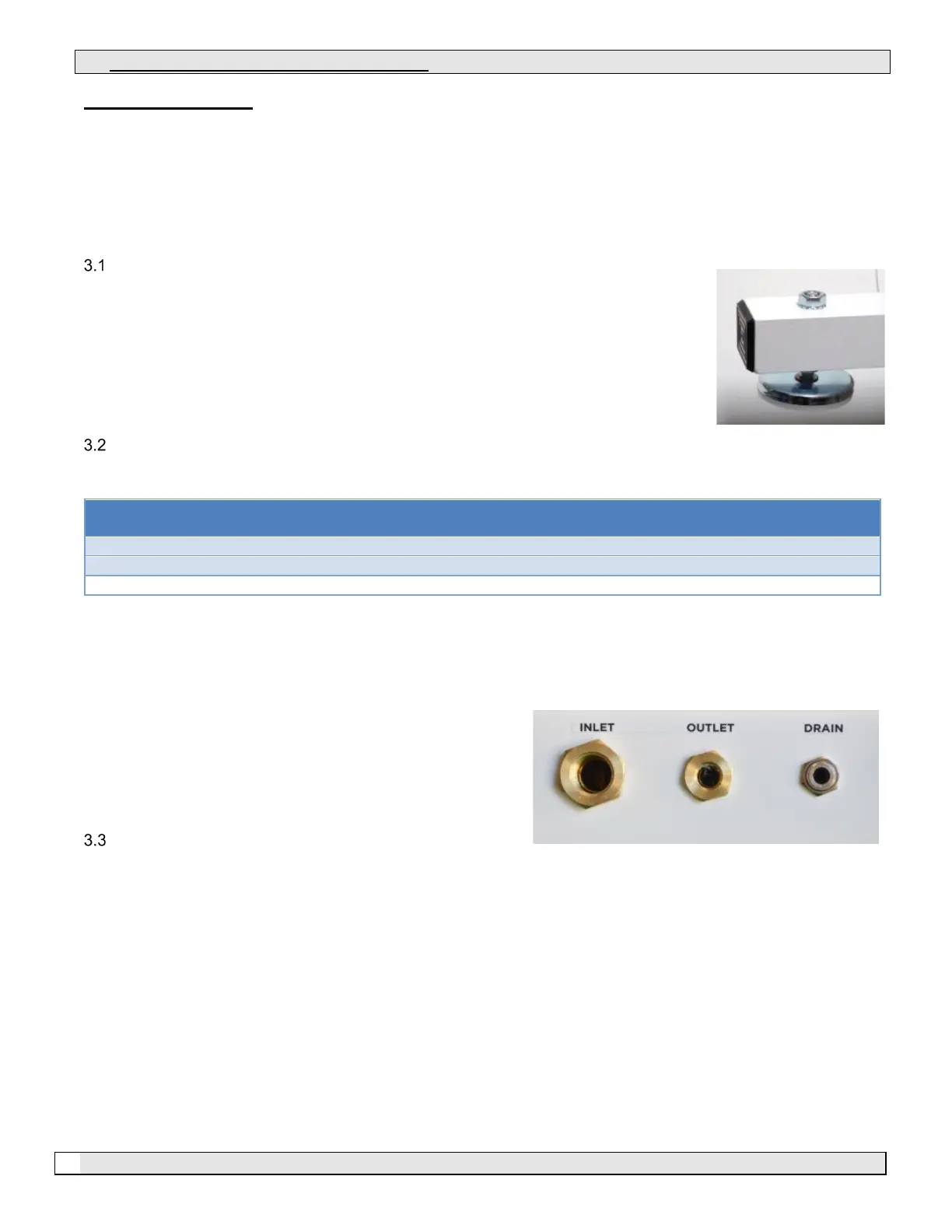
A concrete floor or a concrete slab is ideal. Attach the supplied adjustable feet and plugs
to the legs of the pump as shown in the photograph (right). Using a level, make sure that
the IBEX unit sits as level and plumb as possible.
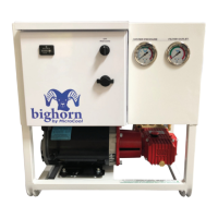
WATER SUPPLY AND CONNECTION
The water supply should be capable of 1.5 times the maximum flow of the pump as shown in the table below.
Correct water pressure and flow rate are essential to pump operation. All pump modules require a minimum of 20
P.S.I. (1.40 BAR) and a maximum of 90 P.S.I. (6.20 BAR) while in operation. The pressure should always be constant
and not fluctuate outside these ranges, especially on system start up. All pump modules are equipped with a low
pressure inlet water fault delay timer, which allows small drops in pressure, but will ultimately “fault off” if low pressure
is present for more than a few seconds.
Ensure that either copper or PVC pipe is used to provide the
correct water supply to the IBEX unit. Never use steel or
galvanized steel fittings. Always use the largest diameter pipe
practical.
DRAINAGE FROM THE PUMP
After the pump module shuts down, the water remaining in the manifold lines will drain out through the pump module
and through the end of the atomization lines on some lines. Ensure that the drain outlet is routed to a suitable
drainage point to avoid flooding. A 6 foot (1.8 M) low pressure drain tube is provided for this purpose. This hose
can be extended as necessary.