EasyManua.ls Logo

MICRODOS MP2-HT CL - User Manual

MICRODOS MP2-HT CL
73 pages
Go to English
Print Icon
To Next Page IconTo Next Page
Loading...
MANUALE DI PROGRAMMAZIONE IT
PROGRAMMING INSTRUCTIONS UK
MANUEL DE RÉGLAGE FR
MANUAL DE REGULACIÓN ES
_____________________MP2-HT CL

Table of Contents

Question and Answer IconNeed help?

Do you have a question about the MICRODOS MP2-HT CL and is the answer not in the manual?

Overview

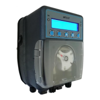
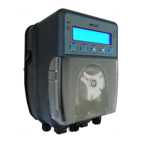
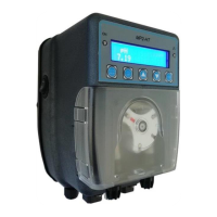
The Microdos MP2-HT CL is a dosing pump designed for water purification, specifically for dosing chlorine in pools, medium, and large systems. It is ideal for maintaining a constant chlorine concentration between 0.2-2.00ppm. The pump offers various operating modes: Manual, ON-OFF, and Proportional, with a flow rate adjustable from 10% to 100% of the maximum capacity. The peristaltic pump's rotation speed can be varied to adjust the flow rate.

Function Description:

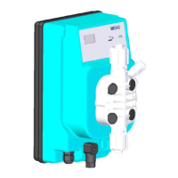
The MP2-HT CL features a standard menu for defining the alarm threshold and setting a "Delay On" function, which activates the measurement before dosing. It also includes an optional "TAL" (Time Alarm) for overdose protection. The pump is equipped with a peristaltic tube break sensor, which, in case of chemical leaks, blocks dosing and can optionally trigger a relay output for alarm repetition (e.g., flow alarm, level alarm, peristaltic hose breakage).

The device's front panel includes an LCD 16x2 character display with backlight.

  • LED Green: Indicates "Pump ON" or "Pump in Alarm" (blinking).
  • LED Red: Indicates chemical dosing.
  • Enter/Menu Button: Used to enter programming or save changes.
  • ESC/SBY Button: Exits the menu or puts the pump in Stand-by mode.
  • Up/Down Arrows: Navigate through menus or modify parameter values.
  • Prime Button: Primes the pump.

General Functions:

  • CL visualization.
  • Instantaneous flow rate display.
  • 3 possible dosing types: Manual, ON/OFF, Proportional.
  • Menu in 4 languages: Italian, English, French, Spanish.
  • Password insertion.
  • Delay on ignition.
  • TAL overdose alarm.
  • Prime button.
  • Relay alarm (dry contact) output for repeating alarms.
  • Restoration of default parameters and factory calibration.
  • Dosing stop (Stand-by).
  • Water flow sensor alarm.
  • Product end level control.
  • Enable input for dosing.
  • Broken tube sensor.
  • Over and under range signal of the measure visualization.

Technical Specifications:

  • Power supply: 90-250V~50-60Hz.
  • Enable input: Dosing consent (110Vac; 230Vac; 24Vdc). Optional.
  • Connectors: For CL probe, level sensor, alarm output (3 and 4 contacts), flow sensor (3 and 4 contacts).
  • ON-OFF switch: Optional.
  • Dosing: Proportional.
  • Setpoint: 1.20ppm.
  • V.Max (maximum threshold): 0.20ppm.
  • Flow.Max (maximum flow rate): 80%.
  • Delay On: 3 seconds (0-999sec).

Usage Features:

The MP2-HT CL offers various display modes for dosing:

  • Manual: Measures 1ppm, with a flow rate of 20% of the maximum.
  • Proportional: Measures 1ppm, with a flow rate of 20% of the maximum.
  • On/Off: Measures 1ppm, with a flow rate of 20% of the maximum.

Stand-by (Stop) Function:

Pressing the ESC/SBY button for 3 seconds puts the pump in Stand-by mode. The pump stops dosing, the green LED blinks, and the display shows "Stby" with a 0% flow rate. Pressing ESC/SBY again returns the pump to the programmed function.

Prime Button:

Pressing the PRIME button briefly puts the pump in Prime status. The pump doses at 25% of maximum flow rate, the green LED is fixed, the red LED blinks, and the display shows "Prime 25%". Pressing PRIME again returns the pump to the operating state. Prolonged pressing of the PRIME button for 2 seconds will dose at 80% of the maximum flow rate, and the display will show "Prime 80%".

Level Probe Control (Optional):

The closing of the level input dry contact causes the pump to stop dosing, the green ON led blinks, and the display shows "Level" with a 0% flow rate. When the level contact opens again, the pump returns to working mode compatible with the actual inputs. The level alarm suspends (but does not reset) the counting of the TAL (Over dosage Time Alarm).

The main menu allows access to:

  • Set Up: Language, display contrast, password, activation/deactivation of Enable input (dosing enable), and peristaltic hose breaking sensor.
  • Dosing: Type of dosing (Manual, Proportional, ON-OFF).
  • Calibration: Chlorine probe calibration.
  • Utility: Programming or non-delay alarm, TAL overdose alarm, flow sensor type, factory parameters reset, and probe calibration.
  • Relay: Alarm relay operation (N.O or N.C), inclusion/exclusion of various alarm types (Delay On, TAL, Flow, UR-OR, Stand by, Level, Enable, Hose break).

Language Selection:

In the Set Up menu, select "Language" with the cursor and press ENTER. Choose "English" with the up/down arrows and press Enter.

Password Protection:

The password protects the modification of the Dosing, Utility, and Relay menus. It does not block Calibration and Set up.

  • First definition: In Set Up, select "Password" and press ENTER. Enter a 4-digit password using the up/down arrows and press ENTER.
  • Change password: In Set Up, select "Password" and press ENTER. Enter the old password, then the new password.

Enable (Optional):

The enable input (230Vac-110Vac) gives power to the pump to dose. In swimming pool plants, this input is connected in parallel with the recirculation pump power supply so that if the filtration is stopped, the pump cannot dose. In order not to damage the electronic board, do not connect the enable directly in parallel with the recirculation pump power supply, but always use a contactor / relay (see installation manual). If your pump has the enable option (see position B page 23: CONNECTIONS), you can choose to activate this input or not.

Broken Hose (Optional):

A sensor detects if the peristaltic tube is torn and leaks chemical to come out. When the broken hose alarm starts, it stops the dosage and the green LED flashes, and the display shows "broken hose". Before any intervention, disconnect the pump from the mains supply! During operation, always use personal protective equipment recommended by the warnings of use of the dosed chemical. For example, use gloves, apron, glasses, etc. The peristaltic hose must therefore be changed. The sensor area inside the pump housing must also be rinsed and carefully dried. See the explanatory image on the side. To exit from this alarm, push the ESC button. Once the operation has been carried out safely, the pump can be restarted. NB: IF THE PUMP IS SWITCHED OFF DURING THE BROKEN HOSE ALARM, WHEN IT WILL BE SWITCHED ON AGAIN IT WILL REMEMBER THE PREVIOUS ALARM. TO EXIT FROM THE BROKEN HOSE ALARM, SHORTLY PUSH THE ESC BUTTON.

Utility Menu:

The Utility menu allows programming the Delay On, the overdose TAL alarm, choosing the type of flow sensor used (Normally Open or Normally Closed), resetting the factory programming of the parameters, and factory probe calibration.

  • Delay On: The delay time is in minutes (from 0-99minutes) that the pump waits after its power on and at the end of a flow alarm to dose the chemical. During this time, the display shows the message "Delay On" that alternates with the writing of the operating mode and the flow rate. During this time, the pump cannot dose but it is possible to program parameters and calibrations.
  • TAL: Time Alarm: The time alarm is expressed in units (0-120units) of dosage. One unit is equivalent to 1 minute of chemical dosing at 100% of the flow rate. The units counting starts from 0 at the moment when the pump starts dosing after the power on. It increases during dosing. If stops during level alarm and stand_by state, it is reset when the power supply is off, when the measure reaches the setpoint, during the flow, broken hose, and enable alarm. When the counting reaches the value of the parameter stored in the Alarm Time, the pump goes into Time Alarm state.
  • Reset Parameters: Resets all parameters to factory settings.
  • Flow Control (Optional): The closing (or opening, this depends on the programming in Utility menu, default is Normally Open contact) of the flow input contact, free of tension, will cause: 1) the pump stops dosing, 2) the green LED blinks, 3) the display shows "Flow" on the second line which alternates with the writing of the operating mode and the flow rate. When the flow contact returns in normal position, the pump exits from the Flow Alarm state and start the working mode compatible with the actual inputs. If a delay on has been set, at the end of the Flow Alarm the pump will go on delay on. NB: The flow alarm resets the counting of the Alarm Time.

Relay Menu:

The relay output indicates the presence of an alarm. It is a dry contact. The relay reports an alarm by closing the contact or by opening it (default is N.O). See the following paragraph: "Alarm". In the Relay menu, it is possible to decide which alarms can be reported by the relay.

  • Alarm: Selects the desired operating mode of the relay with the up/down arrows and press ENTER. N.O = Normally Open (default value), N.C = Normally Closed.
  • Delay On: Includes or excludes this alarm by up/down arrows and press ENTER.
  • UR-OR: What is the UR-OR alarm? For the measurement, it is possible to establish an UR = Under Range threshold for the measure below which the display will show the UR alarm message. In both cases, the relay will signal the alarm by closing or opening depending on the setpoint of the "Alarm" parameter. This type of alarm does not influence the dosing of the pump.

Dosing Menu:

The Dosing menu allows choosing the type of dosing: MANUAL, PROPORTIONAL, ON-OFF.

  • Manual: The pump doses constantly at the programmed flow rate.
  • Proportional: The pump automatically decides whether to dose or not and modulates its flow rate depending on the value of the measurement with respect to the desired value (Setpoint).
  • ON-OFF: The pump automatically decides whether to dose or not depending on the value of the measurement with respect to the desired value (Setpoint). The dosage flow rate is fixed and programmed in the menu.

Maintenance Features:

Calibration:

The device supports calibration for both Amperometric Chlorine Probe and Potentiostatic Chlorine Probe.

  • Amperometric Chlorine Probe Calibration:

    • Description: The probe consists of a flow sensor, water inlet/outlet, tap water sample, float, flow regulation, and chlorine sensor.
    • Recommendations for a Correct Gain Calibration:
      1. Stabilize the flow by turning the knob until the float stays in the upper position.
      2. Prepare the right water flow rate, stabilize the pH at the working conditions (7.0pH and 7.3pH).
      3. The calibration gain is performed at CL concentration values nearest possible to the desired setpoint (e.g., 1.20ppm).
      4. Use a DPD1 photometric test to check the chlorine concentration in the water sample taken from the Tap.
    • Calibration Process:
      1. Perform a DPD1 test on a water sample from the tap.
      2. Press ENTER/MENU for 3 seconds, then use up/down arrows to scroll to "Calibration" and press ENTER.
      3. Scroll to "Gain" and press ENTER. The display shows the reading. Push ENTER and then modify (if necessary) the value shown until it reaches the DPD1 test value. Confirm with ENTER.
    • Offset Calibration:
      1. Disconnect the chlorine probe input from the pump.
      2. Wait until the display reaches a stable reading (any value).
      3. Press ENTER/MENU for 3 seconds, then use up/down arrows to scroll to "Calibration" and press ENTER.
      4. Scroll to "Offset" and press ENTER. The display shows the reading. Push ENTER and then modify (if necessary) the shown value at 0ppm. Confirm with ENTER.
  • Potentiostatic Chlorine Probe Calibration:

    • Description: The probe consists of a flow sensor, water inlet/outlet, tap water sample, float, flow regulation, and chlorine sensor.
    • Recommendations for a Correct Gain Calibration:
      1. The chlorine potentiostatic probe must be positioned at least 1 cm from the bottom of the probe holder.
      2. Avoid bubble formation on the surface of the chlorine probe's membrane.
      3. Stabilize the flow by turning the knob until the float stays in the upper position.
      4. Stabilize the pH at the working conditions (7.0pH and 7.3pH).
      5. The calibration gain is performed at CL concentration values nearest possible to the desired setpoint (e.g., 1.20ppm).
      6. Use a DPD1 photometric test to check the chlorine concentration in the water sample taken from the tap.
    • Calibration Process:
      1. Perform a DPD1 test on a water sample from the tap.
      2. Press ENTER/MENU for 3 seconds, then use up/down arrows to scroll to "Calibration" and press ENTER.
      3. Scroll to "Gain" and press ENTER. The display shows the reading. Push ENTER and then modify (if necessary) the value shown until it reaches the DPD1 test value. Confirm with ENTER.
    • Offset Calibration:
      1. Disconnect the chlorine probe input from the pump and short-circuit pins 2 and 3 on connector C (using a screwdriver).
      2. Wait until the display reaches a stable reading (any value).
      3. Press ENTER/MENU for 3 seconds, then use up/down arrows to scroll to "Calibration" and press ENTER.
      4. Scroll to "Offset" and press ENTER. The display shows the reading. Push ENTER and then modify (if necessary) the shown value at 0ppm. Confirm with ENTER.

Important Note on Zero Calibration:

Zero calibration is executed at the factory. It is not necessary and not recommended! The pump is designed so that the electrical zero probe calibration is equal to electrochemical zero calibration. If it's really necessary to calibrate the zero of the probe, follow the instructions above.

MICRODOS MP2-HT CL Specifications

General IconGeneral
BrandMICRODOS
ModelMP2-HT CL
CategoryMeasuring Instruments
LanguageEnglish

Related product manuals