FlowPrep 060 Selecting the Input Power
May 2010 2-3
6. Position the fuse block so that the side containing the fuse(s) is facing the power module
and insert it into the connector. Do not close the cover.
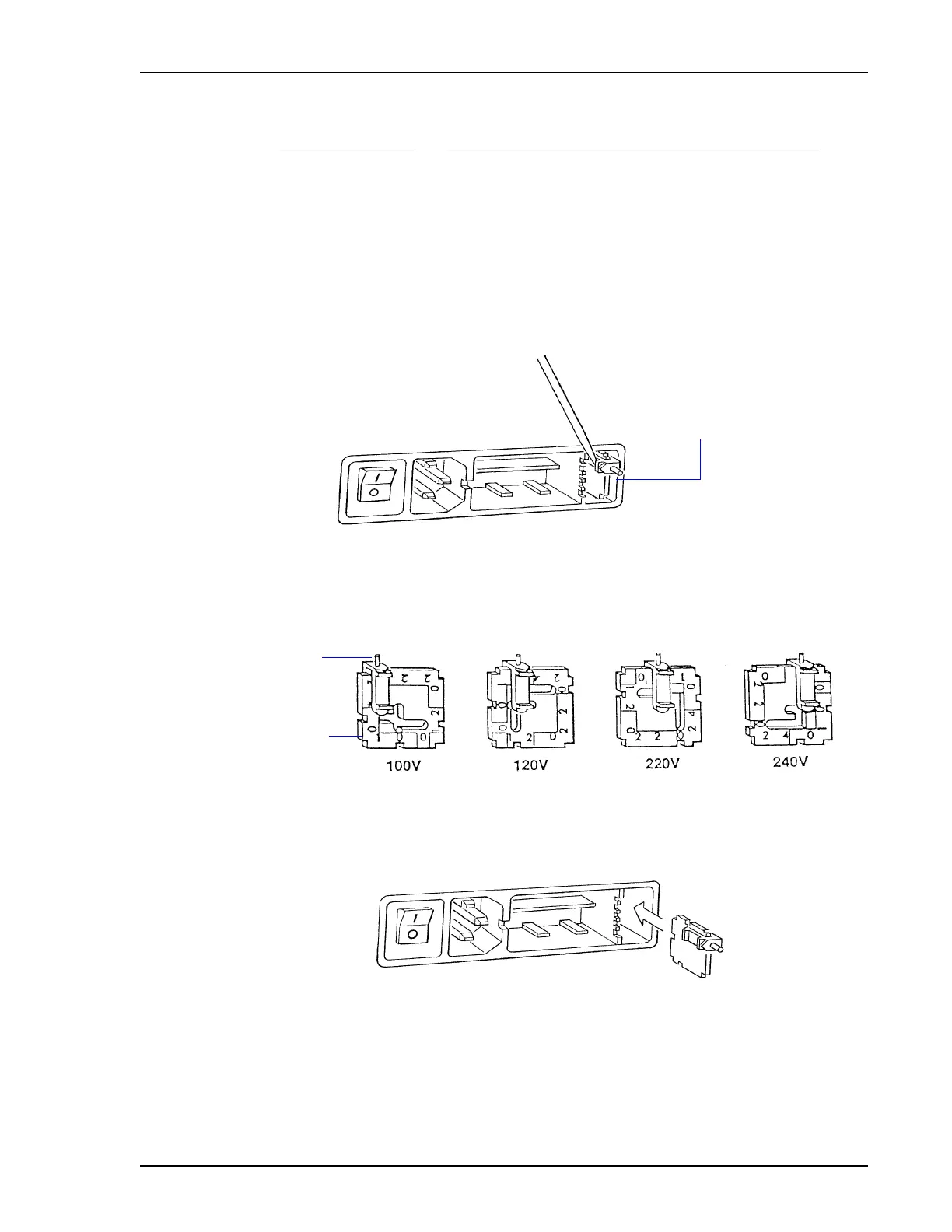
7. Pull the voltage selector card straight out of the power connector housing.
8. Orient the voltage selector card so that the desired voltage is indicated at the bottom.
Orient the indicator pin so that it points upward as shown in the following illustration.
9. Insert the voltage selector card into the power connector housing with the edge containing
the desired voltage first and with the printed side facing the POWER ON/OFF switch.
10. Close the cover to the power entry module; ensure that the indicator pin is in the correct
position.
Power Source Fuse
100-120 VAC 2.5 Amp, slow blow (requires one)
200-240 VAC 1.25 Amp, slow-blow, Type T Time lag, (requires two)
Voltage selector card
Indicator Pin
Voltage