16 (30)
Document no.
99-99-111
Version
6
Date
2003-10-16
Sign.
ToNo
Thyristor
Thyristor active LED
Service plug
Cooling-
Pump/aux
LED
Relay
Active
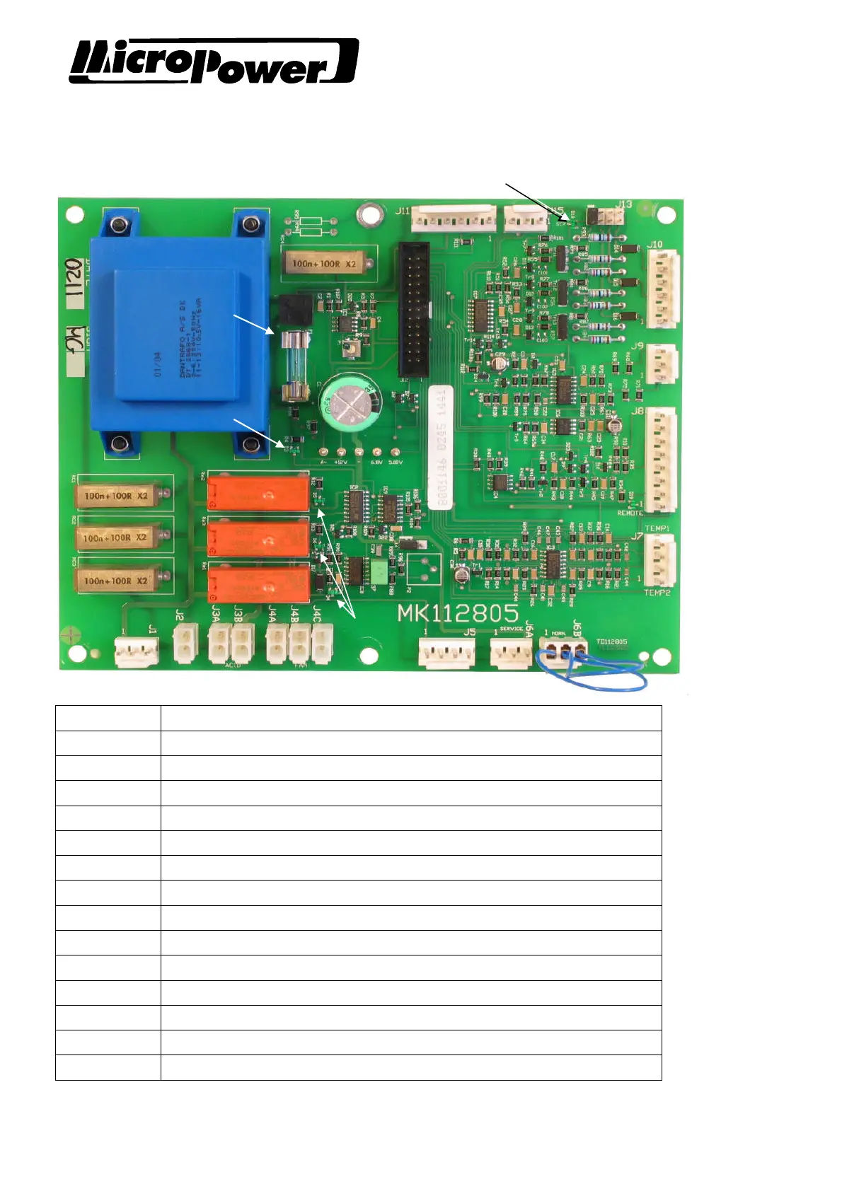
4 SERVICING AND MAINTENANCE
4.1 Main pcb
Connection Function
J1 Power supply 170-260VAC
J2 Contactor control
J3A-B Acid circulation pump output / Auxiliary relay output
J4A-C Cooling fan power
J5 Thermostat input (over temperature protection)
J6A-J6B Service connector
J7 Temperature sensor input (1-2 cooling fin, 3-4 transformer/choke)
J8 Remote start input, shunt signal, analogue 0 and battery voltage.
J9 Input for phase detector
J10 Thyristor gate output
J11 Power supply for optional pcb (I/O-pcb, IDB-transceiver)
J12 Processor c.b. connection (flat ribbon cable)
J13 Thyristor test jumper.
J15 Gate control for extra thyristors (6-pulse)
 Loading...