PD-IM-7648 Evaluation System - User Guide
Copyright © 2013 Microsemi 15
Rev 1.0 / 25 Dec 13 Analog Mixed Signal Group
1 Enterprise, Aliso Viejo, CA 92656, USA; Phone (USA): (800) 713-4113, (ROW): (949) 221-7100 Fax: (949) 756-0308
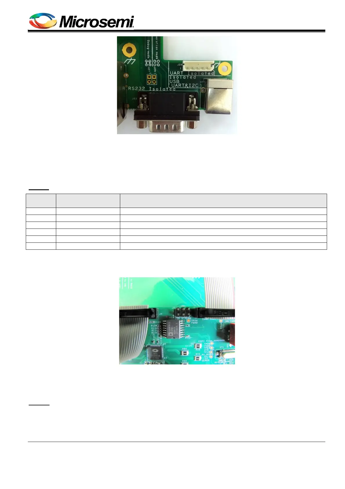
Figure 15: Isolated UART Interface
9. LEDs Indication (see Figure 16)
This interface controls port status indication LEDs. Using four dedicated signals, LEDs indicate port status (on, off,
and so on)
DB: J1
Pin No. Signal Name Description
Data LED signal running to LED indication board ('b' – buffered signal).
Clock LED signal running to LED indication board ('b' – buffered signal).
Latch LED signal running to LED indication board ('b' – buffered signal).
Enable LED signal running to LED indication board ('b' – buffered signal).
Manufacturer: CviLux
Manufacture part number: CH87-142V200
Figure 16: LEDs Indication
10. Daisy Chain (not used)
MB: J8
11. External Power Supplies Indication (see Figure 17)