10
5 – Port Description
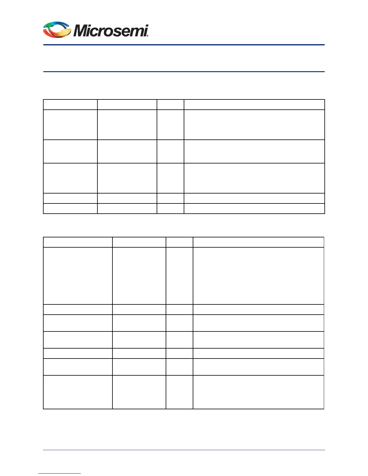
Table 5-1 • ULPI Ports
Port Name Port Group Direction Description
ULPI_DIR USB_ULPI_PADS In Signal controlling the direction of the data bus. The PHY
should drive this signal High when it has data to be
transferred. Otherwise, the PHY should drive this signal
Low.
ULPI_NXT USB_ULPI_PADS In Data control; driven high by the PHY to throttle all data
types except interruption data and the results of register
reads.
ULPI_STP USB_ULPI_PADS Out Data end control; driven High for one XCLK cycle to
signal the end of a transmit operation. It may also be
used to stop the current receive operation. Note:
Asynchronous path from DIR
ULPI_XCLK USB_ULPI_PADS In Transceiver macro-cell clock; 60 MHz
ULPI_DATA<3:0> USB_ULPI_PADS Inout ULPI input/output data bus to ULPI link wrapper
Table 5-2 • UTMI Ports
Port Name Port Group Direction Description
UTMI_LINESTATE[1:0] USB_UTMI_FABRIC In Shows the current state of single-ended receivers.
LINESTATE[0] reflects the state of D+; LINESTATE[1]
reflects state of D-.
00: SE0
01: J State
10: K State
11: SE1
UTMI_XDATAIN[7:0] USB_UTMI_FABRIC In Received data
UTMI_TXREADY USB_UTMI_FABRIC In Transmit data ready; indicates that the transmitter
requires data
UTMI_RXVALID USB_UTMI_FABRIC In Receive data valid; indicates that valid data has been
received
UTMI_RXACTIVE USB_UTMI_FABRIC In Indicates that a valid packet is being received
UTMI_RXERROR USB_UTMI_FABRIC In Indicates that he packet being received is about to be
aborted due to an error
UTMI_VBUSVALID USB_UTMI_FABRIC In VBus compared to selected VBus valid threshold
(required to be between 4.4 V and 4.75 V)
1: Above the VBus valid threshold
0: Below the VBus valid threshold