EasyManua.ls Logo

Microzone MC8RE-V2 - User Manual

Microzone MC8RE-V2
6 pages
Print Icon
To Next Page IconTo Next Page
Loading...
www.microzone.cn
DIGITAL PROPORTIONAL R/CSYSTEM
2.4GHz
FHSS
Please read the instruction manual before use
PRODUCT MANUAL
MC8RE-V2
Question and Answer IconNeed help?

Do you have a question about the Microzone MC8RE-V2 and is the answer not in the manual?

Summary

Functional Diagram and Connections

Technical Specifications

Operational Details

Power On Procedure

Connect the positive and negative terminals to the power supply to turn it on.

Indicator Light Meanings

Explains the meaning of the indicator light's blinking states for status.

Frequency Pairing Instructions

Steps to pair the receiver with the remote control for signal synchronization.

Fail-safe Functionality

Describes receiver behavior upon signal loss, including output values.

Failsafe Switching Method

Details how to change the runaway protection value for channel 3.

Runaway Protection Configuration

PWM Signal Output Specs

Explains the output pulse width and cycle for PWM signals.

SBUS Signal Protocol Details

Important Safety Precautions

Overview

The Microzone MC8RE-V2 is a 2.4GHz FHSS (Frequency Hopping Spread Spectrum) digital proportional R/C system receiver designed for various remote-controlled applications, including fixed-wing aircraft, multi-axis drones, cars, and boats. This product manual provides detailed information on its functional parsing, technical specifications, and usage instructions.

Function Description

The MC8RE-V2 receiver is designed to receive signals from a compatible Microzone remote control (C7-MINI/8B-MINI/Classic-10) and translate them into control signals for various servos and other components. It supports both PWM (Pulse Width Modulation) and SBUS (Serial Bus) signal outputs, offering flexibility for different control setups.

Frequency Pairing: To establish a connection between the receiver and the remote control, a frequency pairing process is required. After powering on the receiver, press the frequency control button. The indicator light will flash quickly, signifying that the receiver has entered frequency control mode. Subsequently, turn on the remote control. Once the pairing is successful, the receiver's indicator light will turn on steadily, indicating normal signal reception.

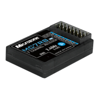
Signal Output: The receiver provides 7 PWM signal outputs and 1 SBUS signal output. Additionally, it features 1 external voltage input.

  • PWM Signal: The PWM signal operates at a high level of 3.3V, with a cycle of 14ms. The output pulse width ranges from 1000-2000us when not mixing, and 880-2120us when mixing or trimming bias.
  • SBUS Signal: The SBUS signal operates at a high level of 3.3V with a 100k baud rate. It uses 8 data bits (9 bits selectable in STM32), even parity (EVEN), and 2 stop bits. Each frame of data is 25 bytes long, starting at 0x0F and ending at 0x00, with a frame duration of 14ms. The data structure is [0x0F] [data0] [data1] [data2] [data3] ... [data10] [flag] [0x00]. Data1 to Data22 correspond to 16 channels (ch1-ch16), with each channel being 11-bit and having a data value range of 200-1800. For docking SBUS signals, hardware inversion of the level is required, as software inversion is not supported. An inversion circuit diagram is provided in the manual.

Fail-safe Function: In the event of accidental signal loss, the receiver automatically switches to a runaway state. During this state, the receiver outputs specific values on certain channels: 1500us on channels 1, 2, and 4, and 900us on channel 3. Other channels remain unchanged. For products manufactured after 2023, a failsafe switching function is available, which changes the runaway protection value of channel 3 to 1500us. To activate this, turn off the receiver, short-circuit channels 5 and 6 with a wire, power on the receiver for three seconds, then remove the wire and restart the receiver.

Default and Customized Runaway Protection: The factory default runaway protection sets channel 3 to 900us and other channels to 1500us. Users can switch to a user-defined runaway protection by long-pressing the frequency pair button on the receiver for more than 15 seconds. The receiver indicator light will flash to confirm the switch.

Important Technical Specifications

  • Model: MC8RE-V2
  • Color: Teal transparent
  • Applications: Fixed wing/Multi-axis/Car/Boat
  • Channel Output: 7 PWM signals, 1 SBUS signal, 1 external voltage input
  • Frequency Range: 2401MHz-2478MHz
  • Control Range: >1000m
  • Receiver Supply Voltage: DC: 4.5-6V
  • Voltage Return: Support
  • SBUS Signal: Support
  • Frequency Pairing Mode: Contact to frequency
  • Recovery Performance: Fast signal recovery
  • Runaway Protection Settings: Support
  • Remote Control Support: C7-MINI/8B-MINI/Classic-10
  • Antenna Type: External dual antenna
  • Antenna Length: 150mm
  • Size: 462514 (mm)
  • Weight: 10g

Usage Features

Power On: Connect the positive and negative terminals to the power supply to turn on the receiver.

Indicator Description:

  • Slow blinking: No signal.
  • Indicator light always on: Signal reception is normal.
  • Fast blinking: Frequency pairing is in progress.

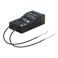
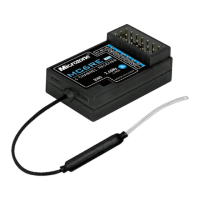
Antenna Placement: The receiver features external dual antennas, which should be positioned to ensure optimal signal reception and range.

Maintenance Features

The manual emphasizes several precautions to ensure the safe and proper operation of the device:

General Safety:

  • This product is not a toy and is not suitable for children under 12 years old. Adults should exercise caution when operating it in the field.
  • Avoid using the device in harsh weather conditions such as evenings, thunderstorms, snow, or when battery levels are low.
  • Do not use the remote control in snowy or watery places, as rainwater ingress can short-circuit the circuit.

Signal Interference:

  • Signal interference can cause loss of control. Avoid areas near mobile phone signal transmission towers, high-voltage power lines, communication broadcasting antennas, military radar launch towers, and complex wireless communication environments.
  • Maintain a clear line of sight between the model and the remote control, as obstacles can block the signal.

Pre-flight Checks:

  • Before use, ensure that the remote control and model are correctly installed and that all steering gear actions and controls operate in the correct direction. Incorrect setup can lead to damage to the model or engine.

Battery Management:

  • If the remote control distance becomes too far or the battery voltage is insufficient, signal loss may occur. When the remote control's "POWER" indicator flashes and an alarm sounds, replace the battery promptly.

Power-off Sequence:

  • Always cut off the power supply to the receiver before turning off the remote control. If the remote control is turned off first, the receiver may remain powered on, potentially leading to loss of control or the engine continuing to operate, which can cause serious accidents.

User Responsibility:

  • Improper use can lead to serious injury or death. Users are advised to carefully read and follow all instructions to ensure the safety of themselves, others, and equipment.

Compatibility:

  • The Microzone 2.4G wireless transmission system requires the use of Microzone remote controls and receivers in pairs. It is not compatible with products from other companies.

Microzone MC8RE-V2 Specifications

General IconGeneral
BrandMicrozone
ModelMC8RE-V2
CategoryReceiver
LanguageEnglish

Related product manuals