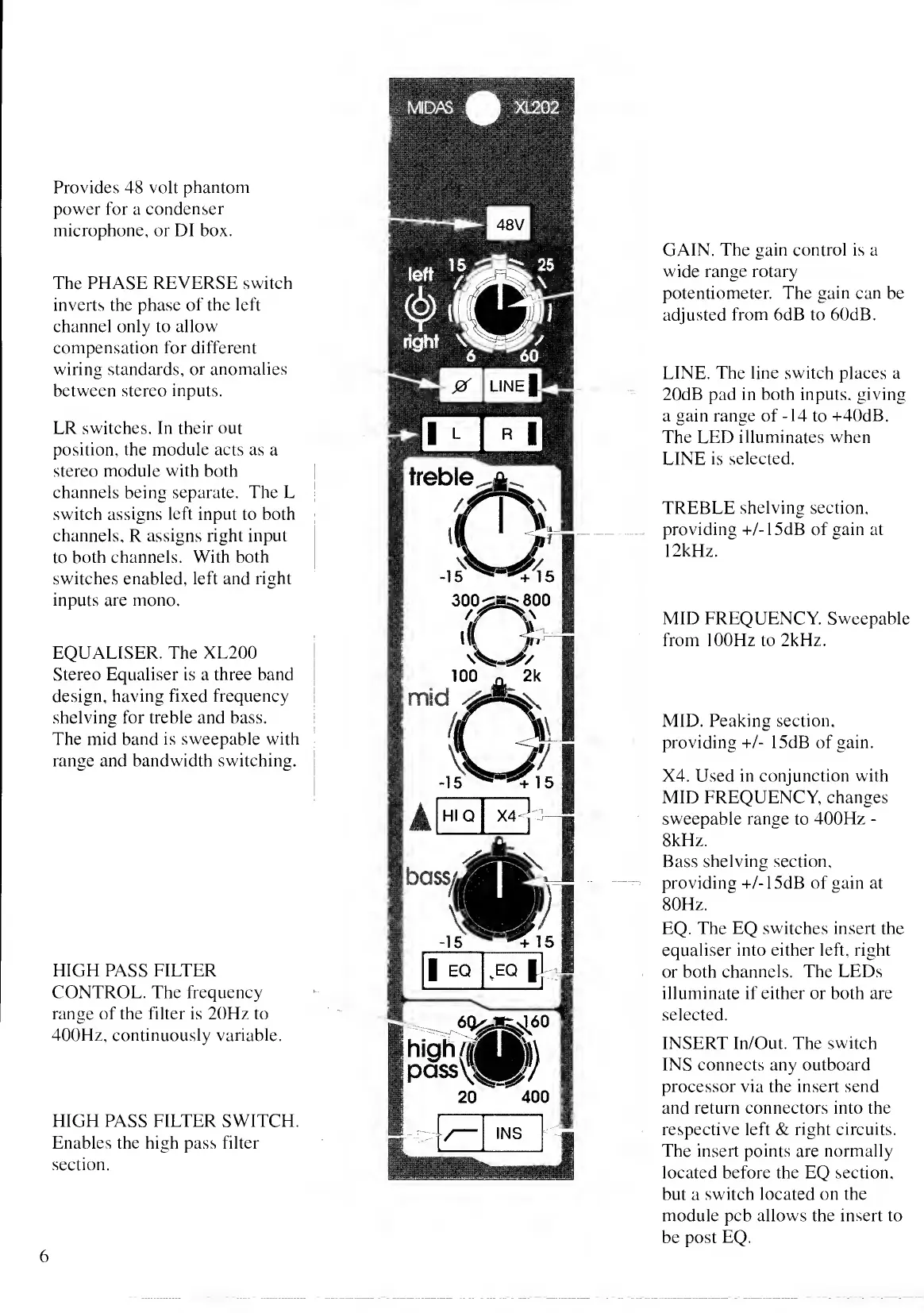
Provides 48 volt
phantom
power for a
condenser
microphone, or DI box.
The PHASE REVERSE switch
inverts the phase
of the left
channel only to allow
compensation for different
wiring standards,
or anomalies
between stereo
inputs.
ER switches. In
their
out
position, the module acts as a
stereo module with both
channels being separate. The
L
switch
assigns left input to both
channels, R assigns
right input
to
both channels.
With
both
switches enabled, left and right
inputs are mono.
EQUALISER. The
XL200
Stereo Equaliser is a three band
design,
having fixed frequency
shelving for treble and bass.
The
mid band is sweepable with
range and bandwidth switching.
HIGH PASS PIETER
CONTROL. The frequency
range of the filter is 20Hz to
400Hz, continuously variable.
HIGH PASS PIETER SWITCH.
Enables the high pass filter
section.
treble
GAIN. The gain control is a
wide range rotary
potentiometer. The
gain can
be
adjusted from 6dB to 60dB.
LINE. The line switch places a
20dB pad in both inputs, giving
a
gain range of
-14
to
-i-40dB.
The
LED illuminates when
LINE is selected.
TREBLE shelving section,
providing -i-/-15dB
of gain
at
12kHz.
MID PREQUENCY. Sweepable
from lOOHz to 2kHz.
MID. Peaking section,
providing +1
-
15dB of gain.
X4. Used in conjunction with
MID PREQUENCY,
changes
sweepable
range
to
400Hz
-
8kHz.
Bass
shelving section,
providing -i-/-15dB of gain at
80Hz.
EQ.
The EQ switches insert the
equaliser into either left, right
or both
channels. The LEDs
illuminate if either or both are
selected.
INSERT In/Out. The
switch
INS connects any outboard
processor via the insert send
and return connectors into the
respective left &
right circuits.
The insert points are normally
located before the EQ section,
but a
switch located on the
module pcb allows the insert to
be post
EQ.
6

 Loading...