Manual Number 9019161 Revision C, August 18, 2023 11
3.3.1 WIRE GAUGE SELECTION
Wire gauge should be 22 AWG. Use of PTFE, ETFE, TFE, Teflon, or Tefzel insulated wire is
recommended for aircraft use per MIL-DTL-16878 or equivalent. Additionally, for data
signals associated with ARINC 429 inputs and outputs, all MIO signals, and RS-
232/422/485, shielded twisted pair wiring per M27500 or equivalent is recommended (and
required to meet the qualifications associated with the product certification.)
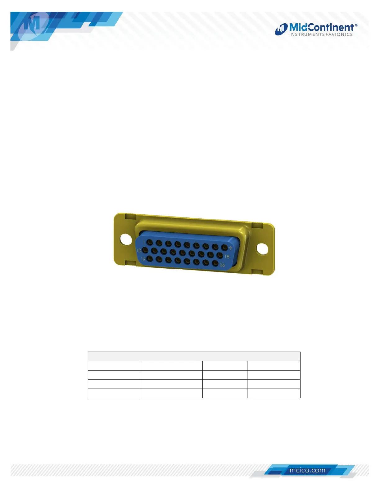
3.3.2 CONNECTOR PINOUT
The supplied connector and backshell is required for proper installation and operation of the
unit. The functions associated with the 26-pin high density D-subminiature connector are
identified in Figure 3.1 and Table 3.2 or Table 3.3 below.
Note that for the -1 Indicator version of the unit (non-pitot/static), six of the MIO pins have
different capabilities. These are referred to as “Frequency Inputs” and are identified as three
separate pairs on pins 23/15, 24/25, and 17/26. Also described below as MIO #7/8, #9/10,
and #11/12. The functions of these pins are detailed further in Section 4.
Figure 3.1 View from Rear of Mating Connector
Contact Tooling Reference
Tool Positronic P/N
Mil P/N
Hand Crimp 9507-0-0-0
M22520/2-01
Positioner 9502-3-0-0
M22520/2-06
Insert/Removal
4811-2-0-0
M81969/1-04
Table 3.1 Contact Tooling Reference
 Loading...