Do you have a question about the Middleby Marshall PS555 series and is the answer not in the manual?
Details the operational sequence for gas ovens, including electrical supply, door, conveyor, blower, and heat switches.
Details the operational sequence for electric ovens, covering electrical supply, door, conveyor, blower, heat, and high limit functions.
Covers blower types and speed adjustments for PS200, PS360, and PS555/570 oven series.
Covers part numbers and servicing for conveyor speed controllers and drive motors.
Details thermocouple part numbers, functions, and troubleshooting procedures.
Provides troubleshooting flowcharts for conveyor motor issues.
Installation instructions for the conveyor speed controller kit with thumbwheel.
Instructions for installing the conveyor speed controller kit with thumbwheel.
Instructions for installing the conveyor speed controller kit for PS200R-series ovens.
Explains temperature controller functions, models, and PID operation.
Installation instructions for the digital temperature controller kit.
Covers high limit control modules for PS200/PS300-series ovens and their functions.
Instructions for a high limit conversion kit for PS300, 310, 350, and 360 ovens.
Instructions for oven thermocouple kits 33984 and 33985.
Covers PS200-series ovens blowers, including part numbers and drive assembly types.
Explains the centrifugal safety switch for burner blower motors.
Details air pressure safety switches for various gas oven models.
Details the centrifugal safety switch for PS360-series burner blower motors.
Instructions for replacing air pressure switch kits 35624 and 35625.
Instructions for replacing an alternate air switch with a specific service kit.
Details gas train components and configurations for PS200-series ovens.
Diagrams and details of the gas train for specific oven models with Midco burners.
Diagrams and details of the gas train for specific oven models with Wayne burners.
Describes the pilot/ignitor assembly and its safety circuit.
Explains pilot flame proof and rectification for gas ovens.
Covers burner blower motor operation, mounting, and safety switches.
Details the combination gas control valve, its components, and adjustments.
Details the ignition module, its part numbers, and wiring.
Provides troubleshooting flowcharts for intermittent pilot systems.
Troubleshooting flowchart for no spark issues.
Troubleshooting flowchart for pilot light failure.
Troubleshooting flowchart for pilot lights and main valve issues.
Instructions for the pilot/ignitor replacement kit.
Procedures for performing a gas leak test after conversion.
Covers PS200-series electric ovens, including heating elements and controls.
Details PS310/360-series ovens, including heating systems and controls.
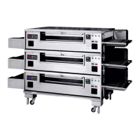
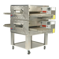
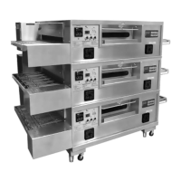
Covers PS555 ovens, including heating systems and element configurations.
| Construction | Stainless steel |
|---|---|
| Frequency | 60 Hz |
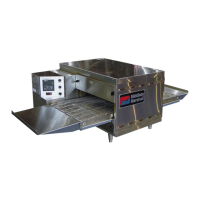
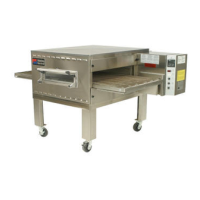
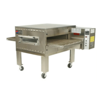
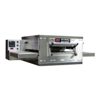
| Type | Conveyor Oven |
| Ventilation Requirements | Required |
| Gas Type | Natural Gas or Propane (depending on model) |