EasyManua.ls Logo

Midea DLFSDAH24XAK User Manual

Midea DLFSDAH24XAK
26 pages
To Next Page IconTo Next Page
Page #1 background imageLoading...
Page #1 background image
Specifications subject to change without notice.
DLFSDA and DLFLDA
INSTALLATION INSTRUCTIONS
Ducted Style Ductless System − Sizes 09 to 58
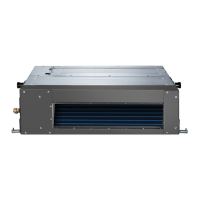
Fig. 1 - Sizes 09−48
Fig. 2 - Size 58
NOTES:
Read the entire instruction manual before starting the installation.
Images are for illustration purposes only. Actual models may differ
slightly.
TABLE OF CONTENTS
PAGE
SAFETY CONSIDERATIONS 2.............................
PARTS LIST 3...........................................
SYSTEM REQUIREMENTS 4...............................
WIRING 4...............................................
DIMENSIONS 5..........................................
INSTALLATION CLEARANCES 7...........................
MAINTENANCE CLEARANCES 7..........................
INSTALLATION LOCATION REQUIREMENTS 8..............
INDOOR UNIT INSTALLATION 8...........................
EXTERNAL STATIC PRESSURE 12.........................
FAN PERFORMANCES AT VARYING STATIC PRESSURES 13....
ELECTRICAL DATA 21...................................
CONNECTION DIAGRAMS 21.............................
START−UP 24............................................
TROUBLESHOOTING 25..................................
Question and Answer IconNeed help?

Do you have a question about the Midea DLFSDAH24XAK and is the answer not in the manual?

Midea DLFSDAH24XAK Specifications

General IconGeneral
BrandMidea
ModelDLFSDAH24XAK
CategoryAir Conditioner
LanguageEnglish

Summary

Safety Considerations

Electrical and Explosion Hazards

Details hazards related to electrical shock and potential explosions.

Equipment Damage and Unit-Specific Warnings

Cautions against improper installation and notes specific unit limitations.

Installation Clearances

Ceiling and Service Access Clearances

Details required space around the unit for installation and access.

Maintenance Clearances

Unit Component Access Clearances

Specifies clearances needed for servicing specific components like blower, coil, and PCB.

Installation Location Requirements

Condensate Drain and Lift Pump Installation

Horizontal Installation Procedures

Steps for connecting condensate lift pump for horizontal units.

External Static Pressure

Fan Performances at Varying Static Pressures

Connection Diagrams

Install All Power, Interconnecting Wiring, and Piping

Start-Up

Test Operation Procedures

Steps for performing a test run after installation.

Troubleshooting

Indoor Unit Diagnostic Codes and Status

Guide to interpreting error codes displayed by indoor unit LEDs.

Related product manuals