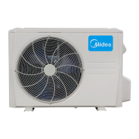
Do you have a question about the Midea DLCERAH12AAJ and is the answer not in the manual?
Details hazards and precautions for electrical shock, emphasizing potential for severe injury or death.
Explains explosion risks, particularly when using oxygen for leak testing, and necessary safety measures.
Outlines precautions to prevent equipment damage or improper operation, such as regarding refrigerant pipe burial.
Table of electrical parameters (MCA, MOCP, RLA, FLA, Rated HP) for cooling-only units.
Table of electrical parameters (MCA, MOCP, RLA, FLA, Rated HP) for heat pump units.
Diagram illustrating the refrigeration cycle, including components for heat pump models.
Procedure for achieving a deep vacuum in the system using a vacuum pump and gauge.
Step-by-step guide for the triple evacuation process using vacuum and nitrogen.
Details on compressor restart delay, temperature protection, fan speed control, and inverter module protection.
Function to detect refrigerant leaks in cooling mode to prevent compressor overload.
Actions taken by the system based on evaporator coil temperature readings (Off, Decrease, Hold, Resume).
Function that detects refrigerant leaks in cooling mode and displays 'EC'.
Important safety note regarding discharging high-voltage capacitors before troubleshooting.
Identification and caution for high-voltage electrolytic capacitors on the PCB.
Procedure and diagram showing the correct position for discharging capacitors.
Table correlating operation/timer lamps with display codes (E, F, P) and LED status for diagnostics.
Schematic of the Printed Circuit Board (PCB) for the 12K 115V outdoor unit.
Table of LED codes indicating unit problems and their corresponding meanings.
Troubleshooting steps for EEPROM parameter errors, including supposed causes and solutions.
Troubleshooting for communication errors between indoor and outdoor units, including wiring and PCB checks.
Procedure to measure DC voltage between specific ports for troubleshooting.
Detailed steps to test DC voltage using a multimeter at L2 and S ports.
Procedure to test the resistance of the reactor, noting normal values.
Troubleshooting steps for errors related to abnormal zero crossing signal feedback.
Troubleshooting steps for errors where indoor fan speed is too low or out of control.
Procedure to check DC fan motor voltage inputs and outputs from the PCB.
Procedure to measure voltage for the indoor AC fan motor to diagnose PCB issues.
Troubleshooting steps for open circuit or short circuit of temperature sensors.
Troubleshooting steps for refrigerant leakage detection, including sensor and system checks.
Troubleshooting steps for overload current protection, including power, blockage, and compressor checks.
Troubleshooting for IPM or IGBT over-current protection, checking wiring, IPM, fan, and compressor.
Troubleshooting steps for over voltage or too low voltage protection, checking power, reactor, and IPM.
Troubleshooting steps for compressor top high-temperature protection, checking airflow and OLP.
Troubleshooting for inverter compressor drive errors, checking wiring, IPM, fan, and compressor.
Procedure to check resistance values of various temperature sensors (T1-T5) using a tester.
Procedure to measure winding resistance of the compressor using a tester.
Procedure to measure IPM continuity resistance between specified terminals.
Procedure to measure the resistance of fan motor windings.
| Energy Efficiency Ratio (EER) | 3.21 |
|---|---|
| Power Supply | 220-240V, 50Hz |
| Refrigerant | R32 |
| Net Weight (Indoor Unit) | 10 kg |
| Net Weight (Outdoor Unit) | 28 kg |
| Type | Split System |
| Capacity | 12000 BTU/h |
| Cooling Capacity | 12000 BTU/h |
| Noise Level (Indoor) | 40 dB |
| Operating Temperature (Cooling) | 18°C to 43°C |


 Loading...