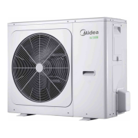
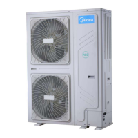
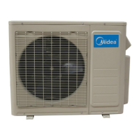
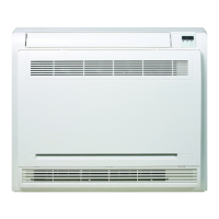
M‐ThermalSplit
72 201909
MideaM‐ThermalSplitServiceManual
Table4‐4.2:ErrorsindicatedonLED1/2
LED1/2flashingpattern Correspondingerror
Flashes8timesandstopsfor1second,thenrepeats L0‐Invertermoduleprotection
Flashes9timesandstopsfor1second,thenrepeats L1‐DCbuslowvoltageprotection
Flashes10timesandstopsfor1second,thenrepeats L2‐DCbushighvoltageprotection
Flashes12timesandstopsfor1second,thenrepeats L4‐MCEerror
Flashes13timesandstopsfor1second,thenrepeats L5‐Zerospeedprotection
Flashes15timesandstopsfor1second,thenrepeats L7‐Phasesequenceerror
Flashes16timesandstopsfor1second,thenrepeats
L8‐Compressorfrequencyvariationgreaterthan
15Hzwithinonesecondprotection
Flashes17timesandstopsfor1second,thenrepeats
L9 ‐ Actual compressor frequency differs from
targetfrequencybymorethan15Hzprotection
PrincipleofDCinverter
①220VACpowersupplychangetoDCpowersupplyafterbridgerectifier.
②Contactorisopen,thecurrentacrossthePTCtochargecapacitor,after5secondsthecontactorclosed.
③ThecapacitoroutputsteadypowersupplyforinvertermodulePNterminals.InstandbythevoltagebetweenPandN
terminaloninvertermoduleis310VDC.Whenthefanmotorisrunning,thevoltagebetweenPandNterminalon
invertermoduleis380VDC.
L0/L4troubleshooting
Situation1:L0orL4errorappearsimmediatelyaftertheoutdoorunitispowered‐on
L0/L4
Invertermoduleisdamaged
1
Yes
Replacetheinvertermodule
2
Notes:
1. MeasuretheresistancebetweeneachofU,VandWandeachofPandNontheinvertermodule.Alltheresistancesshouldbeinfinite.Ifanyofthemare
notinfinite,theinvertermoduleisdamagedandshouldbereplaced.Referto
Figure4‐2.3or4‐2.5inPart4,2.1“OutdoorUnitPCBs”.
2. Whenreplacinganinvertermodule,alayerofthermallyconductivesilicagelshouldbepaintedontheIPMmodule,IGBT,diode,brigderectifier(onthe
reversesideoftheinvertermodule).RefertoFigure4‐4.1.
Power
supply
(220VAC)
L
N
Bridge
rectifier
PTC
Contactor
Inductor
Capacitor
Inverter
module
U
V
W
Compressor
P
N
PFC
○
3
○
1
○
2
 Loading...
