R410A All DC Inverter Mini VRF MCAC-VTSM-2016-10
88 Troubleshooting
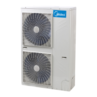
4.15.2 Principle of DC inverter
① 380-415V AC power supply change to DC power supply after bridge rectifier.
② Contactor is open the current across the PTC to charge capacitor, after 5 seconds the contactor closed.
③ The capacitor output steady 540V DC power supply for inverter module P N terminals.
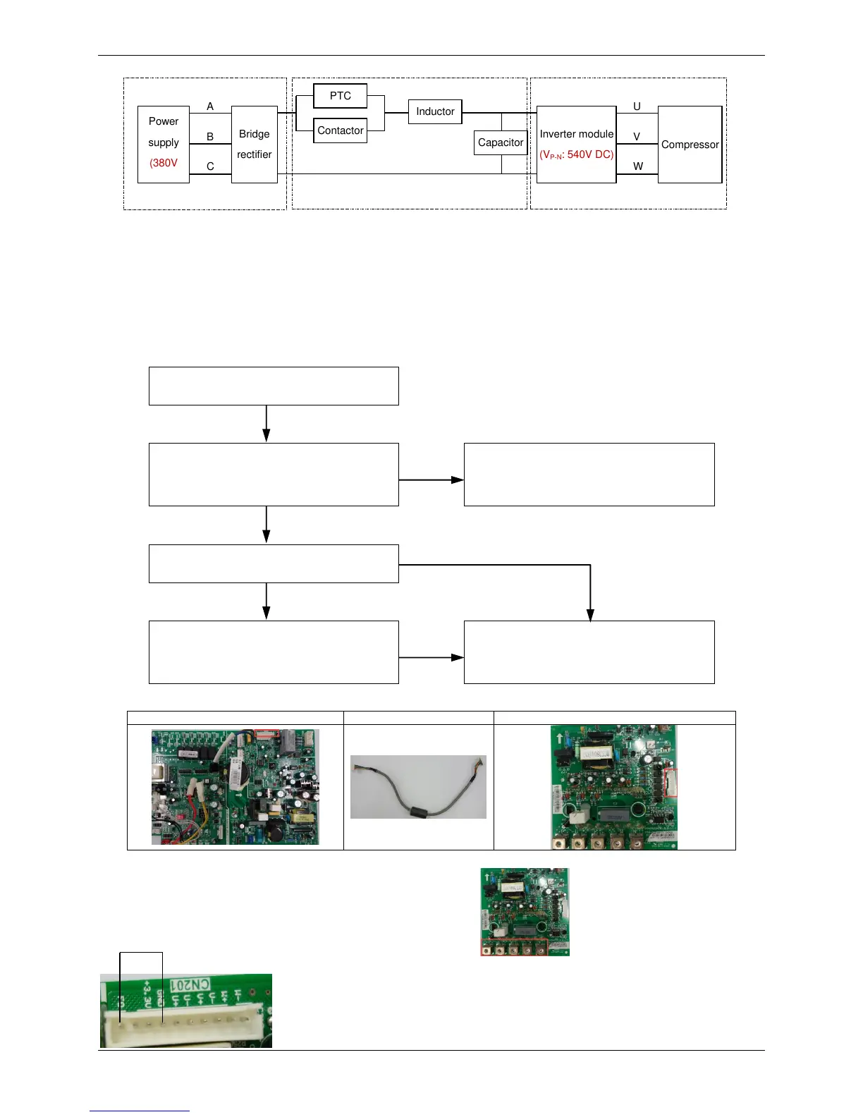
4.15.3 L0 troubleshooting
Condition 1: L0 error appears immediately when the outdoor unit is power on.
Communication wires between main
PCB and inverter module (10 pins) are
not connected properly
1
Ensure communication wires are
connected properly
Inverter module is failed
2
Voltage between F0 and G on
communication wire terminal (10 pins)
on main PCB is too low
2
Replace the inverter module
Notes:
1. Communication wire between main PCB and inverter module:
Communication wire terminal on main PCB
Communication wire terminal on inverter module
2. Measure the resistance between PU/PW/PV/UN/VN/WN on inverter module.
If the resistances are infinite, the U V W terminals are normal.
If the resistances are zero, the U V W terminals have failed.
3. The normal voltage between F0 and GND is 3.1V.
Power
Inverter module
(V
P-N
: 540V DC)
 Loading...