R410A All DC Inverter Mini VRF MCAC-VTSM-2016-10
94 Troubleshooting
3. Check the +15V circuit according to corresponding wiring diagram. If CN5 on inverter module output voltage is not +15V means the
inverter module is failed. If voltage output of inverter module is +15V means main PCB is failed.
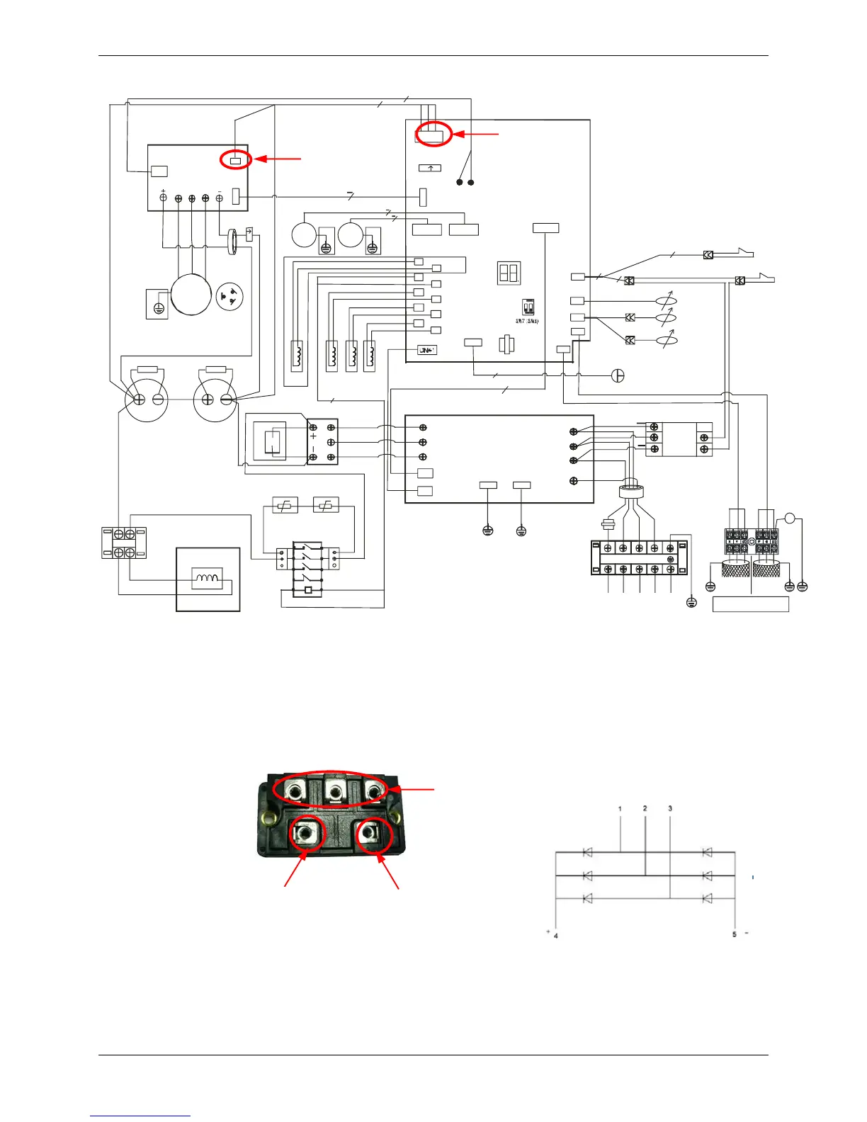
4. To check for three phase bridge rectifier:
Method 1: measure the resistance between any two terminals of the 5 terminals. if any of the resistance is nearly 0, the three phase
bridge rectifier is failed.
Method 2: dial the multimeter to diode gear:
1) Put the red pen in negative pole of DC power output terminal (terminal 5), then put black pen in terminal 1, 2 and 3 in turn. The
voltage should be around 0.378V. If the voltage is 0, the three phase bridge rectifier is failed.
2) Put the red pen in positive pole of DC power output terminal (terminal 4), then put black pen in terminal 1, 2 and 3 in turn. The
voltage should be infinite. If the voltage is 0, the three phase bridge rectifier is failed.
 Loading...