M thermal Mono
46 202005
Midea M thermal Mono Engineering Data Book
4 Electrical Wiring
4.1 General
4.2 Precautions
Fix cables so that cables do not make contact with the pipes (especially on the high pressure side).
Secure the electrical wiring with cable ties as shown in Figure 3-1.14 and Figure 3-1.15. So that it does not come in
contact with the piping, particularly on the high-pressure side.
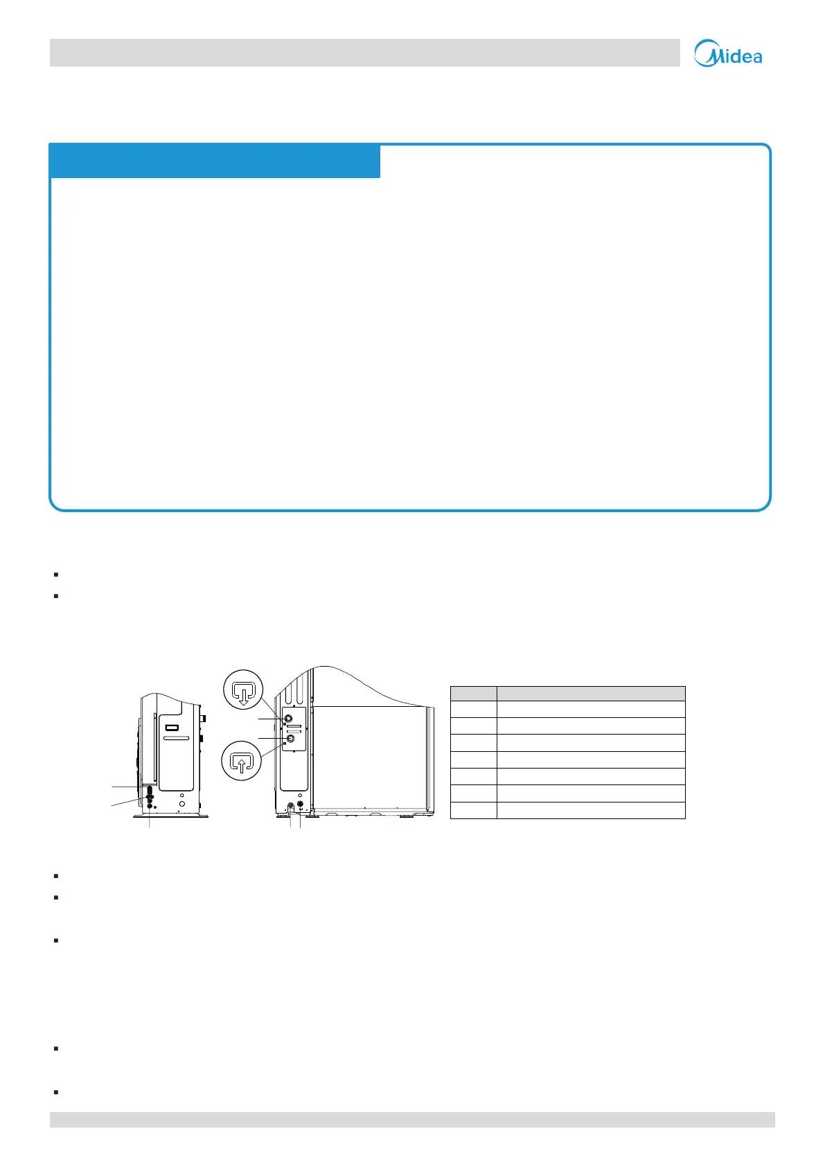
Figure 3-4.1: Wiring hole locations
High voltage or low voltage wire hole
Drainage pipe hole(for safety valve)
Make sure no external pressure is applied to the terminal connectors.
When installing the ground fault circuit interrupter make sure that it is compatible with the inverter (resistant to high
frequency electrical noise) to avoid unnecessary opening of the ground fault circuit interrupter.
This unit is equipped with an inverter. Installing a phase advancing capacitor not only reduce the power factor
improvement effect, but also may cause abnormal heating of the capacitor due to high frequency waves. Never
install a phase advancing capacitor as it could lead to an accident.
4.3 Guidance
Most field wiring on the unit is to be made on the terminal block inside the switch box. To gain access to the terminal
block, remove the switch box service panel.
Fix all cables using cable ties.
All installation and wiring must be carried out by competent and suitably qualified, certified and accredited
professionals and in accordance with all applicable legislation.
Electrical systems should be grounded in accordance with all applicable legislation.
Overcurrent circuit breakers and residual-current circuit breakers (ground fault circuit interrupters) should be
used in accordance with all applicable legislation.
Wiring patterns shown in this data book are general connection guides only and are not intended for, or to
include all details for, any specific installation.
The water piping, power wiring and communication wiring are typically run in parallel. However the
communication wiring should not be bound together with power wiring. To prevent signal interference, the
power wiring and commu
nication wiring should not be run in the same conduit. If the power supply is less than
10A, a separation of at least 300mm between power wiring and communication wiring conduits should be
maintained; if the power supply is in the range 10A to 50A then a separation of at least 500mm should be
maintained.
 Loading...
