M thermal Mono
48 202005
Midea M thermal Mono Engineering Data Book
Table 3-4.1: Wiring requirements
Required number of conductors
Solar energy kit signal wire
Temperature sensor wire for Tw2
Control wire for DHW PUMP
Control wire for 3-way valve
Control wire for 3-way valve
Temperature sensor wire for T5
Control wire for booster heater
Power supply wire for outdoor unit
Control wire for 3-way valve
Notes:
a. Minimum cable section AWG 18 (0.75mm
2)
b. The temperature sensor wire (10m) are delivered with zone 2 outlet tem. Tw2 and domestic hot water tank T5.
c. See Table 3-4.2 for details.
Table 3-4.2: Outdoor unit power supply
Maximum overcurrent protector(MOP)
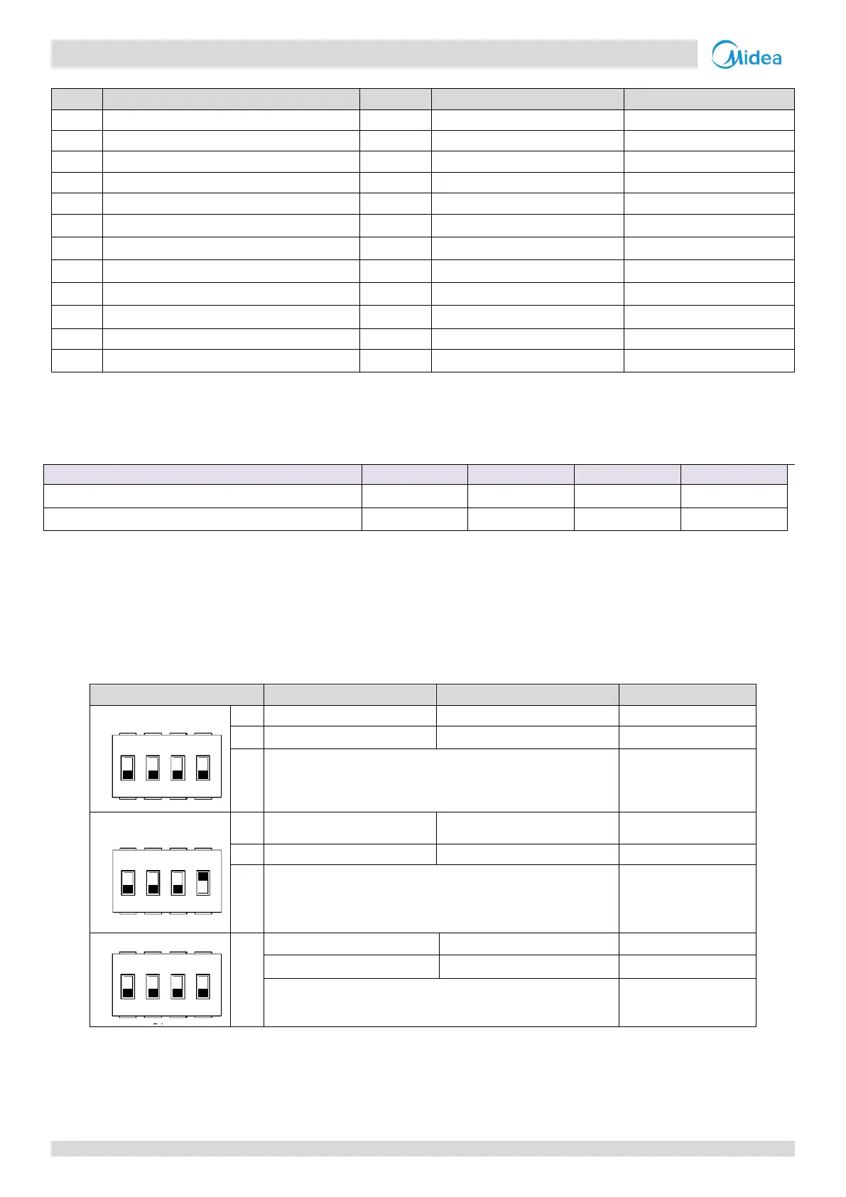
5 DIP Switch Settings
DIP switch is located on the hydraulic module main control board and allows configuration of additional heating source
thermistor installation, the second inner backup heater installation, etc.
Table 3-5.1: DIP switch settings
00=Without IBH and AHS
10=With IBH
01=With AHS for heat mode
11=With AHS for heat mode and DHW mode
Start pumpo after six hours
will be invalid
Start pumpo after six hours will
be valid
00=variable speed pump (Max head:8.5m)
01=constant speed pump
10=variable speed pump(Max head:10.5m)
11=variable speed pump(Max head:9m)
 Loading...