M thermal Mono
60 200204
Midea M thermal Mono Service Manual
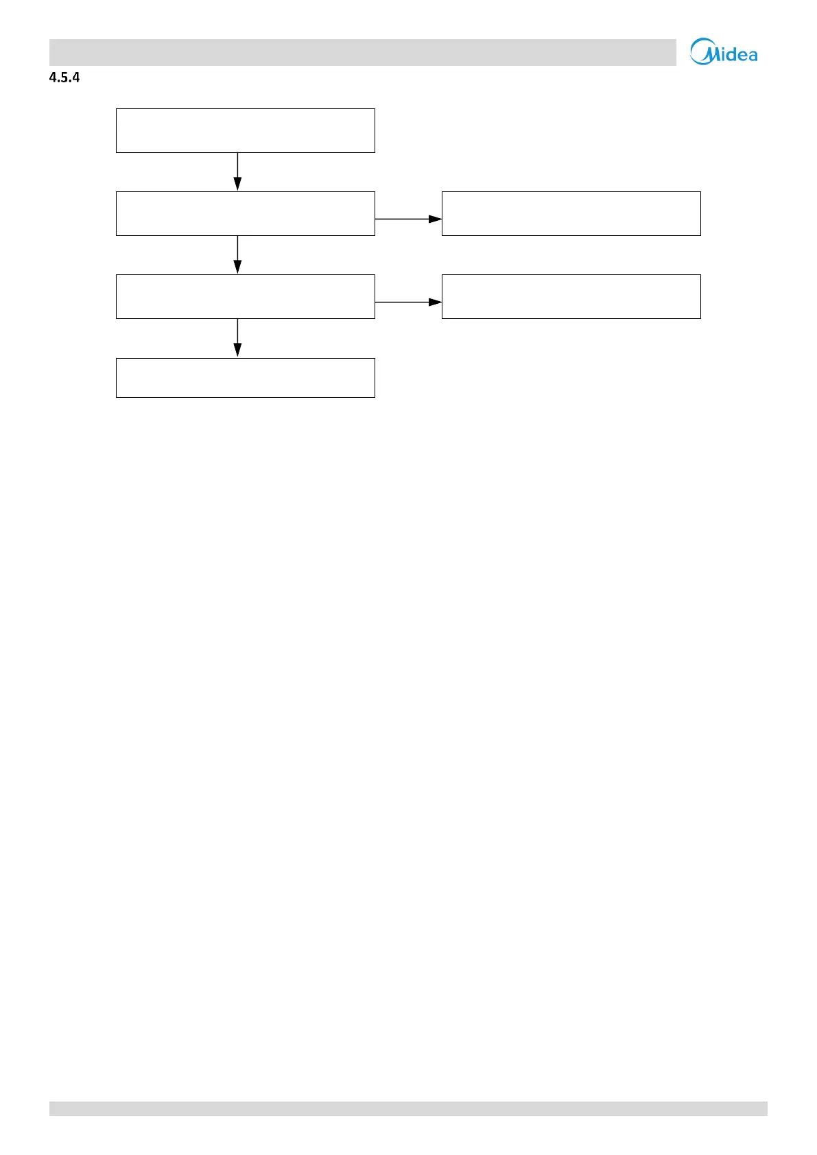
Procedure
E3 / E4 / H2 / H3 / Ed / HA / H5 / H9/ Eb
/ E7 / EC
Temperature sensor connection on
hydronic system main PCB is loose
1
Ensure the sensor is connected properly
Temperature sensor has short-circuited
or failed
2
Replace hydronic system main PCB
Notes:
1. Backup electric heater water outlet temperature sensor, water side heat exchanger refrigerant inlet (liquid pipe) temperature sensor, water side heat
exchanger refrigerant outlet (gas pipe) temperature sensor, water side heat exchanger water inlet temperature sensor and water side heat exchanger
water outlet temperature sensor connections are port CN6 on the hydronic system main PCB (labeled 8 in Figure 4-2.1 in Part 4, 2.2 “Main PCB for
Hydronic System”). Domestic hot water tank temperature sensor connection is port CN13 on the hydronic system main PCB (labeled 9 in Figure 4-2.1 in
Part 4, 2.2 “Main PCB for Hydronic System”). Circuit 2 water outlet temperature sensor connection is port CN15 on the hydronic system main PCB (labeled
10 in Figure 4-2.1 in Part 4, 2.2 “Main PCB for Hydronic System”). Room thermostat connection is port CN3 on the hydronic system main PCB (labeled 28 in
Figure 4-2.1 in Part 4, 2.2 “Main PCB for Hydronic System”).
2. Measure sensor resistance. If the resistance is too low, the sensor has short-circuited. If the resistance is not consistent with the sensor’s resistance
characteristics table, the sensor has failed. Refer to Table 4-5.1 or 4-5.3 in Part 4, 5.1 “Temperature Sensor Resistance Characteristics”.
 Loading...
