M thermal Mono
202004 87
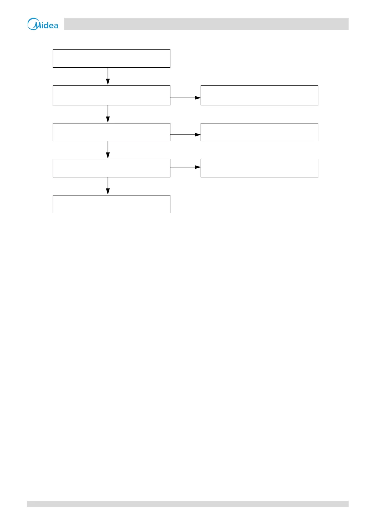
Situation 2: L0 or L4 error appears immediately after the compressor starts up
U V W wire between inverter module and
compressor is not connected properly
1
Ensure U V W wire is connected properly
Inverter module is damaged
2
Replace the inverter module
3
Compressor has malfunctioned
4
Replace the outdoor unit main PCB
Notes:
1. Connect the U V W wire from the inverter module to the correct compressor terminals, as indicated by the labels on the compressor.
2. Measure the resistance between each of U, V and W and each of P and N on the inverter module. All the resistances should be infinite. If any of them are
not infinite, the inverter module is damaged and should be replaced. Refer to Figure 4-2.5 to 4-2.7 in Part 4, 2.1 “Main PCBs for Refrigerant System,
Inverter Module”.
3. When replacing an inverter module, a layer of thermally conductive silica gel should be painted on the IPM module, IGBT, diode brigde rectifer (on the
reverse side of the inverter module PCB). Refer to Figure 4-4.2.
4. The normal resistances of the inverter compressor are 0.7-1.5Ω among U V W and infinite between each of U V W and ground. If any of the resistances
differ from these specifications, the compressor has malfunctioned.
 Loading...
