M thermal Mono
202004 89
L1/L2 troubleshooting
The normal DC voltage between terminals P and N on inverter module is 1.4 time of AC power supply in standby , the DC
voltage is 377V when the fan motor is running. If the voltage is lower than 160V, the unit displays L1. If the voltage is
higher than 500V, the unit display L2.
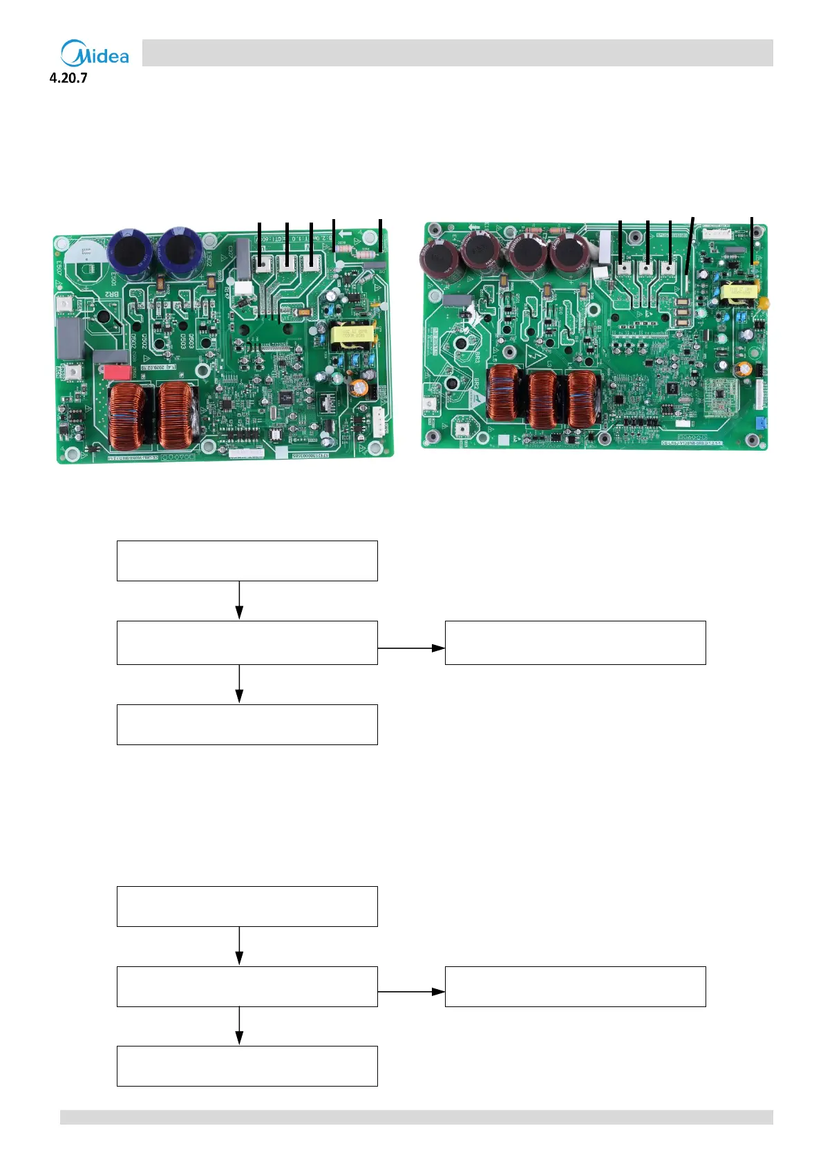
Figure 4-4.3: Inverter module terminals
Inverter module terminals (4-10KW) Inverter module terminals (12-16KW)
Situation 1: L1 or L2 error appears immediately after the outdoor unit is powered-on
Re-start the unit once the power supply
has returned to normal
Replace the inverter module
1
Notes:
1. When replacing an inverter module, a layer of thermally conductive silica gel should be painted on the IPM module, IGBT, diode, brigde rectifer (on the
reverse side of the inverter module PCB). Refer to Figure 4-4.2.
Situation 2: L1 or L2 error appears after the compressor has been running for a period of time and the compressor
speed is over 20rps
Relay on outdoor unit main PCB is open
Replace the outdoor unit main PCB
Replace the inverter module
2
 Loading...
