Do you have a question about the Midea MSC-24HRN1 and is the answer not in the manual?
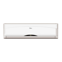
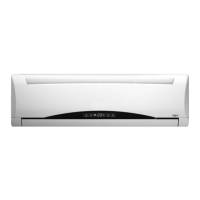
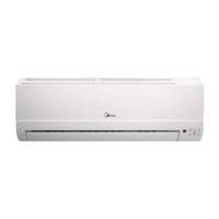
Diagrams and dimensions of the indoor unit.
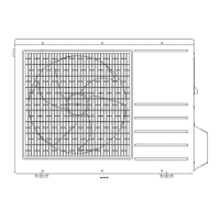
Diagrams and dimensions of the outdoor unit.
Defines operating temperature ranges for cooling.
Defines operating temperature ranges for heating.
Electrical schematic of the indoor unit control board.
Wiring diagrams for indoor and outdoor units.
Specifies torque values for installation fittings.
Guidelines for connecting power and control cables.
Recommended pipe lengths and elevation differences for installation.
Procedure for removing air from the refrigerant lines.
Procedure for recovering refrigerant before re-installation.
Procedure for re-purging air after installation.
Procedure for balancing refrigerant charge.
Process of creating a vacuum in the refrigeration system.
Procedure for charging the system with refrigerant.
Pressure data for MSC-28CRN1 model under various conditions.
Pressure data for MSC-28HRN1 model under various conditions.
Capacity data for MSC-21CRN1 model.
Capacity data for MSC-21HRN1 model.
Capacity data for MSC-24CRN1 model.
Capacity data for MSC-24HRN1 model.
Explains symbols and codes used for electronic functions.
Lists and describes various electronic functions of the unit.
Details the protection mechanisms of the unit.
Details the operation of the fan-only mode.
Describes the cooling mode operation and 4-way valve action.
Explains the dehumidifying mode operation and protections.
Details the operation of the heating mode.
Describes the conditions and actions for defrosting mode.
Explains how the unit automatically selects operating modes.
Details how to activate and use forced cooling.
Describes the sleep mode function for cooling, heating, and auto.
Function that restores previous settings after power failure.
Describes the turbo mode for faster temperature adjustment.
Optional PLASMA function details.
Optional Anion function details.
Explanation of display indicators and their meanings.
Table of failure phenomena and corresponding indicator lamps.
Flowchart for diagnosing detailed malfunctions.
Table listing problems, causes, and remedies.
| Brand | Midea |
|---|---|
| Model | MSC-24HRN1 |
| Category | Air Conditioner |
| Language | English |