V8 Mini R410A VRF 50Hz
85
Part 3 - System Design and Installation
3.4 Selecting Piping Diameters
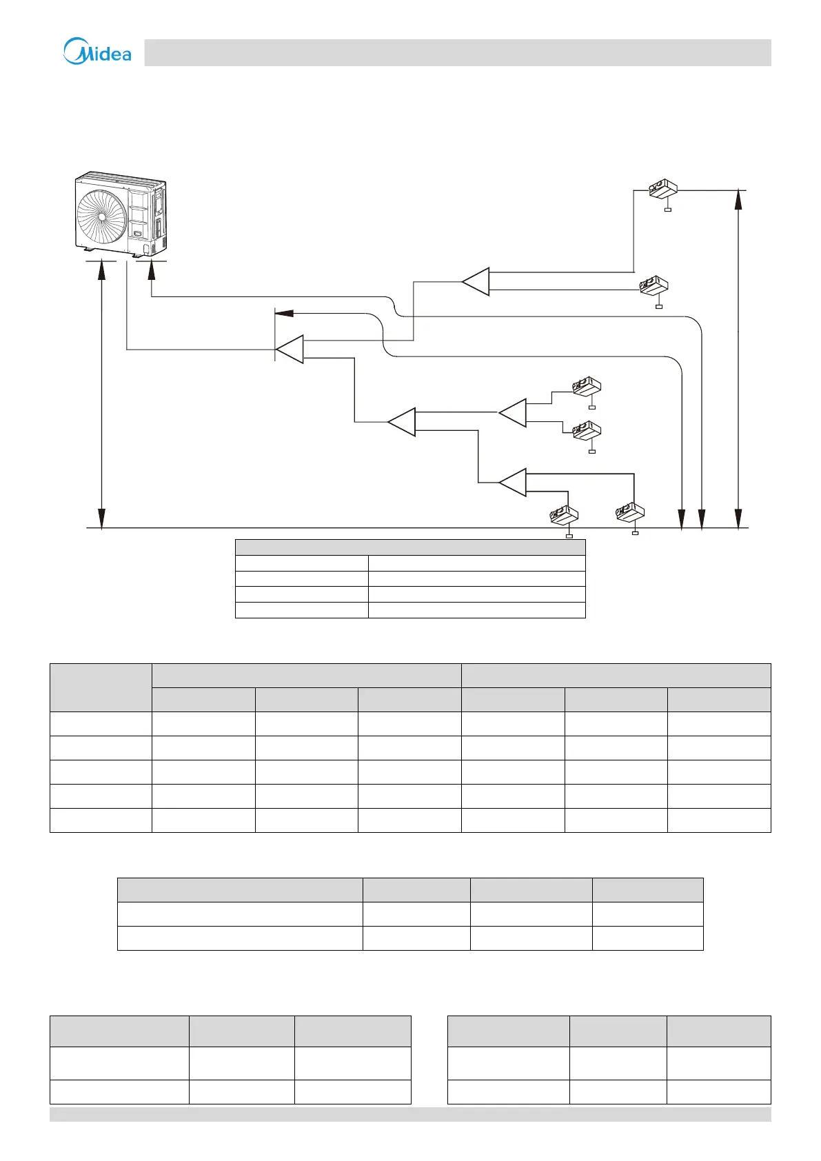
Tables 3-3.4 to 3-3.7 below, specify the required pipe diameters for the indoor and outdoor piping. The main pipe (L1) and
first indoor branch joint (A) should be sized according to whichever of Tables 3-3.4 and 3-3.5 indicates the larger size.
Figure 3-3.3: Selecting piping diameters
Table 3-3.4: Main pipe (L1) and first indoor branch joint (A)
Total equivalent length of liquid pipe and gas pipe< 90m
Total equivalent length of liquid pipe and gas pipe ≥ 90m
Table 3-3.5: Indoor main pipes (L2 to L5) and indoor branch joint kits
Total capacity indexes of indoor units
160 ≤ Capacity indexes < 280
Notes:
1. If indoor main pipes (L2 to L5) are larger than the main pipe (L1), indoor main pipes should reduce to the main pipe’s size.
Table 3-3.6: Indoor auxiliary pipes (a to f)
Table 3-3.7: Pipe diameter of the outdoor unit itself
Capacity of indoor unit
(A×100W)
Outdoor Unit
a
N1
3N
5N
6
N
2
N
4N
b
c
e
f
d
1L
2L
5L
3
L
4
L
A
B
C
D
E
Maximum level difference between the
outdoor unit and indoor unit is ≤ 50 m
Maximum level difference between Indoor
units is ≤ 15 m
Maximum piping length from the first branch joint
to the farthest indoor unit is ≤ 40 m
Maximum equivalent piping length from the outdoor
unit to the farthest indoor unit is ≤ 120 m
First branch
joint