V8 Mini R410A VRF 50Hz
87
Part 3 - System Design and Installation
3.6 Branch Joints
Branch joint design should take account of the following:
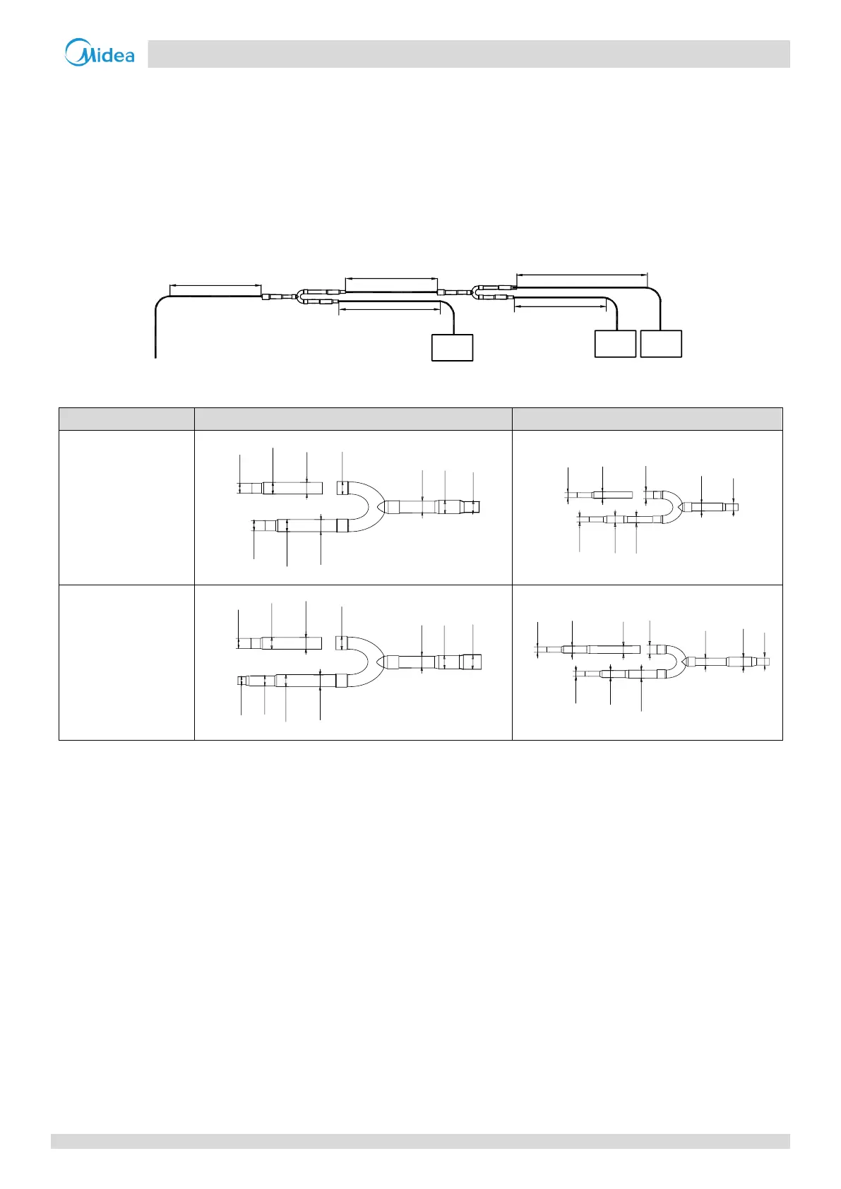
U-shaped branch joints should be used – tee joints are not suitable. Branch joint dimensions are given in Tables 3-3.8.
To ensure even distribution of refrigerant, branch joints should not be installed within 500mm of a 90° bend, another
branch joint or the straight section of piping leading to an indoor unit, with the minimum 500mm being measured from
the point where the branch joint is connected to the piping, as shown in Figure 3-3.5.
Figure 3-3.5: Branch joint spacing and separation from bends (unit: mm)
Table 3-3.8: Indoor branch joint dimensions (unit: mm)
ID:12.7
(ID:15.9)
OD:19.1
ID:19.1
OD:19.1
ID:19.1
ID:15.9
ID:12.7
(ID:15.9)
OD:19.1
OD:12.7
ID:9.5
ID:9.5
ID:6.4
OD:9.5
ID:6.4
OD:9.5
ID:9.5
ID:15.9
(ID:19.1)
OD:22.2
ID:22.2
OD:22.2
ID:22.2
ID:25.4
ID:15.9
(ID:19.1)
OD:22.2
ID:12.7
OD:12.7
ID:6.4
ID:9.5
OD:12.7
OD:12.7
ID:12.7
ID:9.5
ID:12.7
ID:6.4
ID:9.5