VC Pro VRF 50/60Hz
157
Part 3 - System Design and Installation
4.5 Refrigerant Piping Selection Example
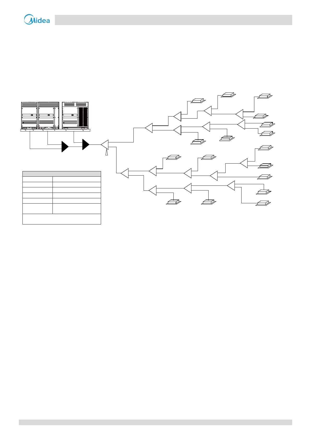
The example below illustrates the piping selection procedure for a system consisting of three outdoor units (32HP + 22HP +
12HP) and 17 indoor units. The system's equivalent length of all liquid pipes is in excess of 90m; the piping between the
farthest indoor unit and the first indoor branch joint is less than 40m in length; and each indoor auxiliary pipe (from each
indoor unit to its nearest branch joint) is less than 10m in length.
Figure 3-4.4: Refrigerant piping selection example
Step 1: Select indoor auxiliary pipes
Indoor units N
1
to N
6
, N
8
to N
11
and N
13
to N
17
are of capacity 5.6kW or greater and their indoor auxiliary pipes are less
than 10m in length. Refer to Table 3-4.8. Indoor auxiliary pipes a to f, h to k, and m to q are Φ15.9 / Φ9.53.
Indoor units N
7
and N
12
are of capacity less than 4.5kW and their indoor auxiliary pipes are less than 10m in length.
Refer to Table 3-4.8. Indoor auxiliary pipes g and l are Φ12.7 / Φ6.35.
Step 2: Select indoor main pipes and indoor branch joints B to P
The indoor units (N
3
and N
4
) downstream of indoor branch joint E have total capacity of 14 + 7.1 = 21.1kW. Refer to
Table 3-4.4. Indoor main pipe L
5
is Φ19.1 / Φ9.53. Indoor branch joint E is FQZHN-01D.
The indoor units (N
1
to N
8
) downstream of indoor branch joint B have total capacity of 14 x 5 + 11.2 + 7.1 + 2.8 = 91.1kW.
Refer to Table 3-4.4. Indoor main pipe L
2
is Φ31.8 / Φ19.1. Indoor branch joint B is FQZHN-03D.
The other indoor main pipes and indoor branch joints are selected in the same fashion.
Step 3: Select main pipe and indoor branch joint A
The indoor units (N
1
to N
17
) downstream of indoor branch joint A have total capacity of 14 x 9 + 11.2 x 2 + 7.1 x 2 + 5.6
x 2 + 2.8 x 2 = 179.4kW. The system's equivalent length of all liquid pipes is in excess of 90m. The total capacity of the
outdoor units is 32 + 22 + 12 = 66HP. Refer to Tables 3-4.4 and 3-4.5. Main pipe L
1
is the larger of Φ41.3 / Φ19.1 and
Φ44.5 / Φ19.1, hence Φ44.5 / Φ19.1. Indoor branch joint A is FQZHN-05D.
Step 4: Select outdoor connection pipes and outdoor branch joints
The master unit is 32HP and the slave units are 22HP and 12HP. Refer to Table 3-4.6. Outdoor connection pipes g1 is
Φ25.4 / Φ12.7, g2 is Φ31.8 / Φ15.9 and g3 is Φ38.1 / Φ19.1.
Refer to Table 3-4.6. Outdoor connection pipe G
1
is Φ41.3 / Φ22.2.
There are three outdoor units in the system. Refer to Table 3-4.7. Outdoor branch joints S and R are FQZHW-03N1E.
N1
(140)
N4(140)
N9
(112)
N10
(140)
N12
(28)
N13
(140)
N16
(56)
N15
(140)
N3(71)
N7(28)
N6
(140)
N8(140)
N14
(56)
N17
(140)
A
B
I
J
N
K
O
C
F
H
E
L1
L2
L3
L5
L7
L8
L11
L12
L13
L15
L14
L16
L9
a
c
d
f
g
h
j
l
m
n
o
p
q
k
S
R
g1
g2
g3
G1
D
N2
(140)
b
L4
N5
(112)
G
L6
e
N11
(71)
i
L
L10
M
P
W3
(16)
W2
(22)
W1
(26)
Figures in parentheses indicate indoor unit
capacity indexes.

 Loading...


