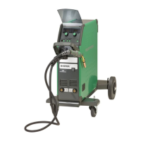
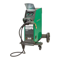
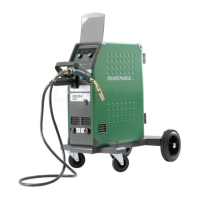
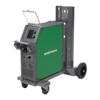
Do you have a question about the Migatronic SIGMA2 300 STBOFF SHORE and is the answer not in the manual?
| Input Voltage | 3 x 400 V |
|---|---|
| Mains Frequency | 50/60 Hz |
| Duty Cycle 60% at 40°C | 300 A |
| Open Circuit Voltage | 17-37 V |
| Protection Class | IP23 |
| Standards | EN/IEC 60974-1 |
| Duty Cycle | 60% at 300 A |
Safety for electrical installation, connection, and maintenance.
Risks from arc emissions, fumes, noise, and workplace conditions.
Precautions against fire hazards and machine positioning.
Measures to avoid disturbing other electrical equipment.
Available welding hoses, cables, and related items.
Information on Intelligent Gas Control and other optional accessories.
Steps for permissible installation, configuration, and generator use.
Safe procedures for lifting and moving the machine.
Connecting the machine to mains power and shielding gas.
Connecting welding torches and electrode holders.
Adjusting wire brake and checking cooling liquid.
Procedures for switching on and initiating welding.
Electrical and performance data of the power source.
Specifications for the wire feed units.
Performance parameters of the cooling unit.
Overview of welding processes and adjustable settings.
Steps for updating the machine's software via SD card.
Handling software updates for connected units on the CAN network.
How to view different software versions on the machine.
Setting up internal or external control modes.
Adjustments possible with dialog, sequence, and remote controls.
Details on the key lock function and its levels.
Configuration and operation of the water cooling system.
Symbols for wire feed overload and overheating.
Faults related to gas pressure and torch cooling.
Indicators for current issues and mains voltage problems.
Symbols for mixed transfer, current faults, and multi-feeder errors.
Error codes encountered during MWF software updates.
Error codes for welding program package updates.
General maintenance requirements and safety advice.
Maintenance for wire cabinet, cooling unit, and power source.
Details on warranty duration, claims, and exclusions.
Overview of manual MIG welding modes and controls.
Explanation of advanced synergic welding modes and functions.
List of spare parts for the Cooling Unit MCU.
Identification of front panel, side panels, and chassis parts.
Identification of trolley parts and mains supply cables.
Identification of screws, clips, and small structural components.
Identification of support arms, lifting devices, and grills.
Identification of belts, chains, and switch components.
Identification of wheel assemblies, couplings, and cables.
Part numbers and lengths for intermediary cables.
Identification of earth and electrode cables.
Identification of inductor, transformer, and power modules.
Identification of fans and their mounting plates.
Identification of Venturi parts, packing, and PCB plates.
Identification of capacitors, clutch sets, filters, and diodes.
Part numbers for MIG Manager and cable coiling kits.
Part number for the remote control kit.
Identification of Dinse PCBs and their wire harnesses.
Identification of mounting plates and programmable logical devices.
Identification of power supply units and fuses.
Identification of water pump, fan blades, and cooler components.
Identification of hose parts, connectors, and hoses.
Identification of output diodes and snubber PCBs.
Identification of flow control parts and harnesses.
Identification of water module harnesses and water tanks.
Options for wire feed rolls and liners based on wire type and diameter.
Information on capillary tubes and available kit sets.
Contact details for Germany, Denmark, Finland, France, Hungary, Italy, Netherlands, Norway, Sweden, UK.
Contact details for Czech Republic and India.
