1.
2.
3.
1.
2.
3.
4.
Enabling - /system gps set enable=yes;
Setting antenna to external - /system gps set gps-antenna-select=external;
Checking configuration - /system gps print.
Configuration information -https://wiki.mikrotik.com/wiki/Manual:System/GPS#Basic_examples
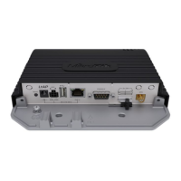
Powering
Direct-input power jack (5.5 mm outside and 2 mm inside, female, pin positive plug) accepts 12-30 V DC with provided 24 V, 1.2 A adapter.
Ethernet port accepts passive Power over Ethernet 12-30 V DC (compensate for the loss on cable, so more than 12 V recommended).
The automotive connector can be used to power the device from regular 12/24 V connections in automobiles and buses. The plug has four pins:
bottom left (black) is the ground, bottom right is power in (red). The upper two (AUX) are reserved for future use.
The power consumption under maximum load can reach 12 W without attachments. Please attach ground (earth) wire to the screw under the door.
Connecting to a POE Adapter: (Not included)
Connect the Ethernet cable from the device to the POE out port of the POE adapter.
Connect an Ethernet cable from your LAN to the POE adapter.
Connect the power cord to the adapter, and then plug the power cord into a power outlet.
Front status LED behavior
Solid Blue – the device is powered on.
Solid Green – user-defined LED, can be configured in system settings.
Solid Green – state of GPS module.
Solid Green– the set of five green LED, shows the signal strength of the cellular network.
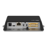
miniPCIe slot
SIM card connectivity
MiniPCIe 1 (top slot) supports PCIe and USB 2.0 cards but is shared with the USB 2.0 type A port (can use either the USB port or miniPCIe slot
at the same time). It can be used only for SIM slot #1.
MiniPCIe 2 (bottom slot) supports only USB (2.0 and 3.0) miniPCIe modems (no PCIe support). Uses SIM slot #2 and SIM slot #3. By default
uses SIM slot #2.
USB 2.0 type A port (can only be used if miniPCIe 1 is not used).
To use the top miniPCIe slot with a USB type miniPCIe card, switch the USB connections to the miniPCIe slot: /system routerboard usb set
type=mini-PCIe This will disable the USB 2.0 port on the front of the unit.
Insert the SIM card into the top slot by a chip on the SIM card facing down. Bottom slots – with the chip facing up.
Please check if you are using the correct SIM slot. For the modem inserted in the bottom mini-pcie slot, you need to use either sim slot 2 or sim slot 3. And
the used sim slot needs to be selected in RouterOS.
CLI command to select the sim slot:
/system routerboard modem set sim-slot=2
Modem installation