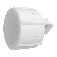
1.
2.
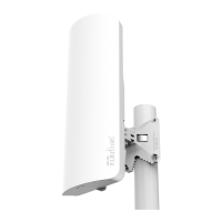
3.
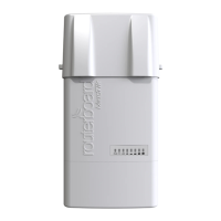
4.
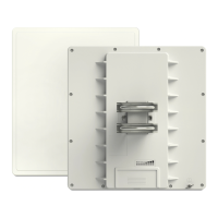
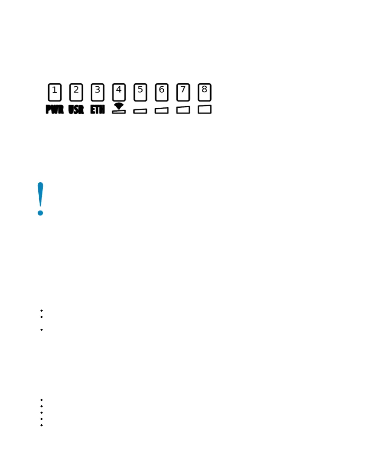
Front status LED behavior
RouterOS allows configuring each LED's activity the way that the user wishes. It is possible to configure the LEDs to display wireless strength, blink the
LEDs on interface traffic activity and many other options. For further information please visit https://wiki.mikrotik.com/wiki/Manual:System/LEDS
Default factory configuration for this device:
Solid Blue – The device is powered on.
Solid Green – User-defined LED.
Solid Green – Active Ethernet port.
8. Solid Green – The set of five green LEDs, shows the signal strength.
Configuration
We recommend clicking the "Check for updates" button in the QuickSet menu, as updating your RouterOS software to the latest version ensures the best
performance and stability. Please make sure you have selected the country where the device will be used, to conform with local regulations.
RouterOS includes many configuration options in addition to what is described in this document. We suggest starting here to get yourself accustomed to
the possibilities: . In case IP connection is not available, the Winbox tool ( ) can be used to connect to the MAC address https://mt.lv/help https://mt.lv/winbox
of the device from the LAN side (all access is blocked from the Internet port by default). Seek additional help from your local trainers or become a trainer of
yourself. https://mikrotik.com/training/about
For recovery purposes, it is possible to boot the device for reinstallation, see section .NetBox 5#Buttons and Jumpers
Reset button
The reset button has three functions:
Hold this button during boot time until LED light starts flashing, release the button to reset RouterOS configuration (total 5 seconds).
Keep holding for 5 more seconds, LED turns solid, release now to turn on CAP mode. The device will now look for a CAPsMAN server (total 10
seconds).
Or Keep holding the button for 5 more seconds until LED turns off, then release it to make the RouterBOARD look for Netinstall servers (total 15
seconds).
Regardless of the above option used, the system will load the backup RouterBOOT loader if the button is pressed before power is applied to the device.
Useful for RouterBOOT debugging and recovery.
Accessories
Package includes the following accessories that come with the device:
EU/US Switching Power Supply 24 V DC , 0.8 A, 19.2 W.
Hose clamp 40/60 w2 A2 9 mm.
2pcs - Plastic tie strap fastener (300 mm(L) 7,6 mm(W)).
Gigabit POE injector cable with shielded connector (RBGPOE).
K-27 din-rail bracket mounting set.
 Loading...