The heater is supplied with a stainless
steel
'L
'
shaped mounting bracket which is
designed to be fitted on a vertical
bulkhead with the heater sat in it
(
see dia
1
.)
The heater has to be mounted in this
way for correct operation
.
22
0
22
o
Examine the chosen mounting place
carefully to make sure that it has enough
strength to support the heater and that it is
free from excessive vibration while the
boat is in use
.
MY
16
:
Fix the mounting bracket to the bulkhead
using the
4
x
3/4
"
No
10
self tapping
screws provided
.
The heater can now be
fitted in place either way round
(
whichever
is the most convenient for the ducting run
)
with the
4
x s
/
s M
6
x
20
set screws
provided
.
MY
30
:
Fix the mounting bracket to the bulkhead
using the
6
x
3/4
"
No
10
self tapping
screws provided and mount the heater
using the
4
x s
/
s M
8
x
20
set screws
.
Now screw the s
/
s exhaust stub into the
bottom of the heat exchanger
,
and slide
the combustion air manifold
'A
'
over the
top
.
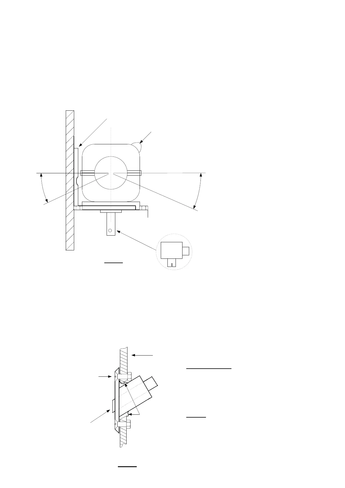
1.
Mounting the heater
.
The heater should be mounted in a well ventilated locker which should be dry and within
2
metres of a suitable site
for the exhaust skin fitting
.
It should also give consideration to servicing and access to cleaning the glow plug
.
The
heater should be mounted in such a way that the axis through the hot air outlet and fresh air inlet is horizontal
.
Bulkhead
s/
s exhaust stub
.
s/
s mounting bracket
glow plug
Permissible inclination angles
.
Dia
1.
2
.
Exhaust and combustion air system
:
The exhaust skin fitting needs to be fitted as far above the water line as possible to prevent any ingress of water into
the
heater
.
An ideal place for the skin fitting is on the transom
.
Once you have planned the siting
,
drill a
4
mm pilot hole as guidance for the pilot drill on the hole saw arbour
.
Now
drill the correct size hole
:
MY
16/
MY
30
=
42
mm
.
When you have completed this re
-
drill the hole at an angle at a slow
speed
(
see dia
2
)
to allow the skin fitting to fit in a snug hole
.
Now drill
4
x
5
mm holes for the fixing bolts
,
apply
silicon to the rear of the face and secure in place with the
4
x M
5
x
40
button head s
/
s screws provided
.
Drill with hole saw at angle
after you have drilled the
perpendicular hole
.
BE CAREFUL
!
Transom
4
x fixing screws
Dia
2.
Fix the s
/
s exhaust to the skin fitting and secure with
the heavy duty clamp
.
Cut the exhaust at a
convenient place to insert the silencer
,
(
MY
30
Only
)
and secure with a tridon hose clip
.
IMPORTANT TIP
: (
MY
30
Only
.)
Put an exhaust clamp
on one end of the remaining exhaust
,
now take the
combustion air manifold and insert the split spigot into
the end
.
Push this assembly onto the exhaust spigot
of the heater making sure that it slides home over the
heat exchanger casting
,
and tighten the clamp
.
The MY
16
does not require an exhaust silencer
.
NOTE
:
THE EXHAUST DOES GET HOT
-
DO NOT
CLAMP IT TO ANY COMBUSTIBLE MATERIALS
.
The exhaust lagging should now be wrapped around
the full length of the exhaust pipe and secured at each
end with the hose clips supplied
.
Silicon sealant
-
2
-
'A'
 Loading...