Do you have a question about the Miller Electric GENERWELD 130 and is the answer not in the manual?
General safety advice and understanding manual procedures.
Covers burn prevention, toxic fumes, fire/explosion, and gas equipment safety.
Details specific safety practices for arc welding operations.
Lists relevant industry standards for welding and cutting.
Manual's purpose for familiarizing personnel with equipment.
Procedures for inspecting equipment upon receipt and filing claims.
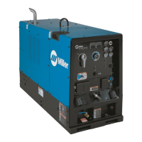
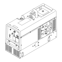
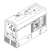
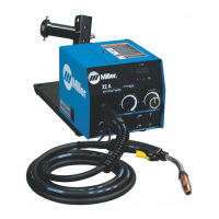
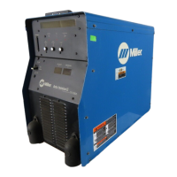
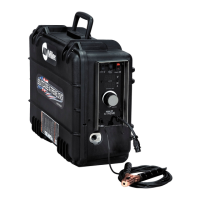
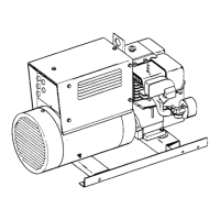
Describes the unit as a gasoline engine-driven welding generator.
Emphasizes reading the safety section before operation.
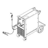
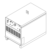
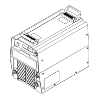
Selecting a proper installation site for the welding generator.
Recommends grounding for auxiliary power plant capability.
Details selecting, installing, and maintaining proper welding cables.
Explanation of the six electrode receptacles and one work receptacle.
Describes the AC duplex receptacle and its circuit breaker protection.
How Volt-Ampere curves show output voltage and current.
Steps for connecting cables and starting the welding process.
Importance of regular inspections and cleaning for economical operation.
Inspection and maintenance of collector ring brushes.
Periodic checks of cable connections and insulation.
Chart to diagnose and remedy common generator troubles.
Checking and maintaining engine oil level for break-in and operation.
Information on the engine's dry element air cleaner.
Recommended fuel grade and precautions for fueling.
How the choke control adjusts fuel-air mixture for starting.
Selecting between IDLE and WELD-POWER engine speeds.
How to use the stop switch to shut down the engine.
Step-by-step procedure for starting the generator engine.
Procedure for safely stopping the generator engine.
Engine oil requirements, change intervals, and capacity.
Importance of keeping the air-cooled engine clean.
Maintenance and cleaning of the spark plug.
| Input Voltage | 120 V |
|---|---|
| Welding Amperage Range | 30 - 130 A |
| Welding Process | Stick (SMAW) |
| Input Phase | Single-phase |
| Open Circuit Voltage | 28 VDC |