J
Jason RamosJul 29, 2025
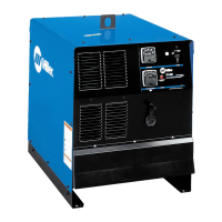
What to do if there is no weld output, the power switch pilot light is on, and the fan is on in my Miller Electric Welding System?
- YymooreJul 29, 2025
If the Miller Electric Welding System unit overheated, allow it to cool with the fan on. If you are using a remote control, put the Output (Contactor) switch in the Remote position and connect the remote control. If the remote is not in use, put the switch in the On position. You may need to check, repair, or replace the remote control. If none of these actions solve the issue, have a Factory Authorized Service Agent check the control board PC1.