M
maciasdebraAug 9, 2025
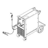
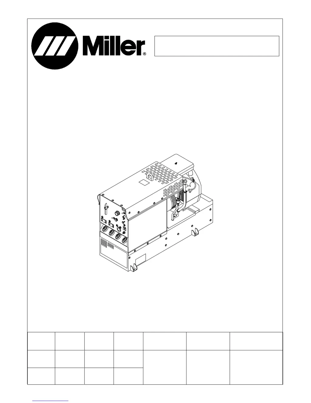
What to do if my Miller Electric Legend AEAD-200LE Welding System has no or erratic weld output?
- KKevin RomeroAug 9, 2025
If your Miller Electric Welding System exhibits no or erratic weld output, begin by cleaning and tightening all weld connections both inside and outside the unit. Verify the engine speed and adjust it if necessary. Ensure that the Ampere Ranges switch S5 is not positioned between settings and check its continuity, replacing it if needed. Inspect the reactor AC-Z for any signs of winding failure, checking continuity across the windings and ensuring proper connections; replace AC-Z if necessary. Check the resistance and connections of the Fine Amperage control R1, which should measure 0 to 30 ohms ± 10%, and replace R1 if necessary. Disconnect leads 21, 23, and 33 from the brushes, and check continuity across slip rings, replacing the rotor if necessary.