Do you have a question about the Miller Electric S-52A and is the answer not in the manual?
Explains the purpose and importance of following safety rules for welding equipment.
Outlines common safety measures applicable to various welding processes and general practices.
Details specific safety guidelines and precautions for arc welding operations.
Lists referenced industry standards for comprehensive safety information.
Provides foundational safety principles and general information for equipment use.
Explains hazard identification symbols and signal words used in the manual.
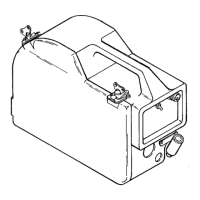
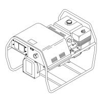
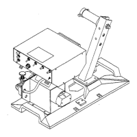
Describes the wire feeder's features, capabilities, and general design.
Guidelines for selecting a suitable installation site for the wire feeder.
Instructions for installing the wire spool hub assembly onto the wire feeder.
Procedures for installing wire guides and drive rolls for proper wire feeding.
Details on connecting the welding gun to the wire feeder for power and gas.
Information on connecting remote controls to the wire feeder's receptacle.
Instructions for connecting the shielding gas supply to the wire feeder.
Procedure for removing the drive motor vent screw before operation.
Guidelines for connecting optional water cooling systems for the welding gun.
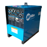
Instructions for connecting the wire feeder to the welding power source.
Steps for installing welding wire spools or reels onto the wire feeder.
Procedure for threading welding wire through the wire feeder.
Describes the function of the main power switch for the wire feeder.
Explains how to adjust the wire feed speed using the control knob.
Details the function of the jog button for manual wire feeding.
Describes the gas purging function activated by the push button.
Explains the switch for retracting or feeding wire when the gun trigger is closed.
Describes the switch for selecting initial slow wire feed speed.
Information on using remote controls via the receptacle and switch.
Explains the optional burnback control feature for wire feeding.
Step-by-step procedure for performing Gas Metal Arc Welding (GMAW) operations.
Instructions for properly powering down the wire feeder and associated equipment.
Schedule and procedures for regular equipment maintenance and upkeep.
How to align drive components for proper wire feeding on two-drive roll models.
Alignment procedures for motor and drive gears on four-drive roll models.
Steps to reinstall the wire spool hub assembly after maintenance or replacement.
Information on circuit breakers and fuses for protecting the unit from overload.
Procedure for checking and replacing motor brushes for proper operation.
Safety guidelines for handling and preventing damage to electronic circuit boards.
Guide to diagnosing and resolving common equipment issues and malfunctions.
Schematic representation of the unit's electrical components and connections.
Detailed wiring connections and layout for the equipment.
| Brand | Miller Electric |
|---|---|
| Model | S-52A |
| Category | Welding System |
| Language | English |