EasyManua.ls Logo

Miller Electric Spectrum 875 - User Manual

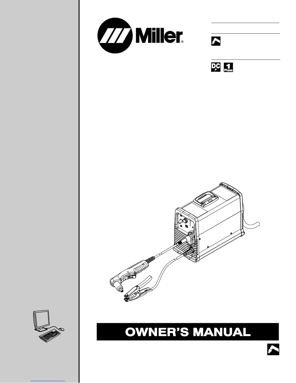
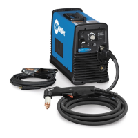
Miller Electric Spectrum 875
44 pages
Print Icon
To Next Page IconTo Next Page
Loading...
Processes
Description
Air Plasma Cutting
and Gouging
Air Plasma Cutter
OM-234 163B 201004
Spectrum 875
And ICE-60T Torch
R
File: Plasma Cutters
Visit our website at
www.MillerWelds.com

Table of Contents

Questions and Answers

  • J
    John GarciaAug 20, 2025
    What to do if the arc goes on and off while cutting with Miller Electric Spectrum 875?
    • J
      James CooperAug 20, 2025
      If the arc goes on and off during cutting, increase the torch travel speed. Also, clean or replace the torch consumables as necessary. Ensure the work clamp is securely attached to a clean, rust-free workpiece.
  • J
    Jonathan KellerAug 22, 2025
    What to do if the arc goes out while cutting with Miller Electric Spectrum 875?
    • P
      Patrick StoneAug 22, 2025
      If the arc goes out while cutting, ensure the work clamp is securely attached to a clean, rust-free workpiece. Make sure the drag shield is on the workpiece or the extended tip is 1/16 in. (1.6 mm) to 1/8 in. (3.2 mm) from the workpiece while cutting. Clean or replace torch consumables as necessary.
  • D
    deborah86Aug 25, 2025
    What to do if sparks come out top of cut or cut is not clean with Miller Electric Spectrum 875 Welding System?
    • J
      Jeffrey MaddenAug 25, 2025
      If sparks come out the top of the cut or the cut is not clean, reduce the torch travel speed. Also, clean or replace torch consumables as necessary, and ensure the work clamp is securely attached to a clean, rust-free workpiece. Note that the unit may not be capable of cutting metals thicker than its rating.
  • M
    Michelle DanielAug 27, 2025
    Why is the temperature status light on for Miller Electric Spectrum 875 Welding System?
    • R
      ralph55Aug 27, 2025
      If the temperature status light is on, the unit may be overheating. Allow the fan to run, and the light should go out once the unit has cooled.
  • V
    Vanessa EdwardsAug 28, 2025
    What to do if I have short tip life with Miller Electric Welding System?
    • T
      Tammy MendozaAug 28, 2025
      To address short tip life, check and clean the drag shield of any slag, particles, and debris. Verify the position of the cut/gouge switch matches the process. Check the input air pressure, and ensure the compressed air is clean, dry, and oil-free, using a filter kit if needed. Maintain a 1/8 in. (3.2 mm) standoff for extended tip cutting over 40 amps and avoid dragging the tip on the workpiece.
  • H
    Henry ContrerasAug 30, 2025
    What to do if the pressure status light is on for Miller Electric Welding System?
    • L
      Lisa YangAug 30, 2025
      If the pressure status light is on, check for sufficient gas/air supply pressure. Also, check for a dirty air filter and replace it if necessary. Inspect the air lines for leaks.
  • C
    conleyanthonySep 1, 2025
    Why is there no pilot arc on my Miller Electric Welding System?
    • L
      Lisa HernandezSep 1, 2025
      If there is no pilot arc or difficulty establishing an arc, clean or replace worn consumables as necessary. Check for a damaged torch or torch cable. Verify the position of the cut/gouge switch matches the consumables being used.
  • S
    Samuel CookSep 3, 2025
    What does it mean when the cup status light is on for Miller Electric Spectrum 875 Welding System?
    • G
      gmoranSep 3, 2025
      If the cup status light is on, check the torch shield cup and reset the power switch.
  • D
    Dakota GardnerSep 5, 2025
    What does it mean when cup status light flashes at a rate of two quick cycles on Miller Electric Welding System?
    • J
      Jessica OrtizSep 5, 2025
      If the cup status light flashes at a rate of two quick cycles and then a one-second pause, no pilot arc was established, meaning the power source failed to maintain a pilot arc. Try a different set of torch consumables (tip and electrode). Check for input pressure between 90-120 PSI.
  • M
    Michael WalkerSep 7, 2025
    How to resolve temperature status light flashing rate steady on Miller Electric Spectrum 875 Welding System?
    • C
      Charles HartSep 7, 2025
      If the temperature status light is flashing at a steady rate, the power source temperature sensor(s) provided inaccurate feedback but have returned to normal. Cycle the unit power off and back on again.

Summary

Section 1 - Safety Precautions

Symbol Usage and Plasma Arc Cutting Hazards

Explains safety symbols and details hazards of plasma cutting.

Section 1 - Safety Precautions

Electrical Shock and Fumes Hazards

Details risks of electric shock, and hazards from fumes and gases.

Plasma Arc, Cylinder, and Noise Hazards

Outlines dangers from plasma arcs, gas cylinders, and noise exposure.

Section 1 - Safety Precautions

Additional Safety Hazards

Details hazards related to hot parts, moving parts, falling equipment, and fire/explosion risks.

EMF, Overheating, and Hydrogen Hazards

Discusses EMF effects, equipment overheating, and hydrogen explosion risks.

Static, HF Radiation, and Arc Interference

Addresses static discharge, HF radiation, and arc cutting interference issues.

Section 1 - Safety Precautions

California Proposition 65 and Safety Standards

Lists California warnings and principal safety standards.

EMF Information and Recommendations

Provides EMF information and recommendations for exposure reduction.

Section 2 - Safety Instructions

Symbols and Plasma Cutting Hazards

Explains safety symbols and hazards of plasma arc cutting.

Fire, Explosion, and Electric Shock Hazards

Details risks of fire, explosion, and electric shock during operation.

Section 2 - Safety Instructions

Electrical Discharge and Part Explosion Risks

Covers risks of lethal electrical discharge and injury from part explosions.

Flying Sparks, Arc Rays, and Noise Hazards

Details dangers from flying sparks, arc rays, and noise exposure.

Fumes, Gases, and Cylinder Hazards

Outlines hazards related to fumes, gases, and pressurized cylinders.

Section 2 - Safety Instructions

Cylinder Explosion and Additional Hazards

Covers cylinder explosion risks and additional hazards during installation/operation.

Moving Parts, Instructions, and Eye Injury Risks

Addresses hazards from moving parts, importance of instructions, and eye injury risks.

Section 2 - Safety Instructions

EMF, Overheating, and Hydrogen Hazards

Discusses EMF effects, equipment overheating, and hydrogen explosion risks.

Falling Equipment, Fire;Explosion, ESD, and Interference

Covers falling equipment, fire, ESD, and interference risks.

Section 2 - Safety Instructions

California Proposition 65 Warnings

Provides California Proposition 65 warnings regarding chemicals.

Principal Safety Standards and EMF Information

Lists principal safety standards and EMF information for exposure reduction.

Section 3 - Definitions

Symbols and Label Definitions

Explains symbols found on the nameplate and serial number/rating label.

Section 4 - Installation

Specifications

Provides detailed technical specifications for the unit's power supply and torch.

Section 4 - Installation

Duty Cycle and Overheating

Details duty cycle percentages and consequences of overheating the unit.

Torch Dimensions

Illustrates the physical dimensions of the plasma torch.

Section 4 - Installation

Power Source Dimensions and Weight

Provides physical dimensions and weight of the power source unit.

Connecting Work Clamp and Gas;Air Supply

Instructions for connecting the work clamp and gas/air supply.

Section 4 - Installation

Connecting and Disconnecting Torch

Step-by-step guide for connecting and disconnecting the torch assembly.

Connecting and Disconnecting Work Cable

Instructions for connecting and disconnecting the work cable plug.

Section 4 - Installation

Power Cable Management Strap

Guide for coiling and securing the power cable using the management strap.

Section 4 - Installation

Electrical Service Guide

Recommendations for electrical service, including fuse ratings and conductor sizes.

Extension Cord Data

Data on extension cord sizing for maximum cord length and fuse ratings.

Section 4 - Installation

Serial Number and Rating Label Location

Identifies the location of the serial number and rating label on the unit.

Location Selection and Input Power Connection

Guidance on selecting a location and connecting the input power.

Section 4 - Installation

Connecting to Generator with Adapter Cord

Instructions for connecting the plasma cutter to a generator using an adapter cord.

Section 4 - Installation

Wiring Optional 240 Volt Plug

Procedure for wiring an optional 240 volt plug for generator connection.

Section 4 - Installation

Generator Settings for Plasma Cutter Operation

Recommends generator settings for optimal plasma cutter operation.

Installing Alternative Plug

Steps for installing an alternative plug if the supplied one differs.

Section 5 - Operation

Controls

Explains the function of each control on the unit's panel.

Section 5 - Operation

Trigger Safety Lock

Details how to use the trigger safety lock feature.

Plasma Cutting System Practices

Outlines best practices for plasma cutting system operation.

Section 5 - Operation

Sequence of Cutting Operation

Step-by-step guide for performing a plasma cutting operation.

Section 5 - Operation

Sequence of Gouging Operation

Step-by-step guide for performing a plasma gouging operation.

Section 5 - Operation

Sequence of Piercing Operation

Step-by-step guide for piercing operations with the plasma cutter.

Section 5 - Operation

Cutting Speed

Provides recommended cutting speeds for various materials and thicknesses.

Consumables Storage Compartment

Locates the compartment for storing consumables and parts.

Section 6 - Maintenance & Troubleshooting

Routine Maintenance

Lists routine maintenance tasks to be performed on the unit.

Checking Shield Cup Shutdown System

Instructions for checking the shield cup shutdown system.

Section 6 - Maintenance & Troubleshooting

Checking;Replacing Consumables

Guide for checking and replacing torch consumables like tip and electrode.

Section 6 - Maintenance & Troubleshooting

Wrapper Removal;Installation

Steps for removing and installing the unit's wrapper cover.

Checking or Replacing Filter Element

Procedure for checking or replacing the air filter element.

Section 6 - Maintenance & Troubleshooting

Status;Trouble Lights

Explains the meaning of various status and trouble indicator lights.

Section 6 - Maintenance & Troubleshooting

Troubleshooting Power Source

Provides solutions for common power source troubleshooting issues.

Section 6 - Maintenance & Troubleshooting

Troubleshooting Torch

Offers solutions for troubleshooting common torch-related problems.

Section 7 - Electrical Diagram

Section 8 - Parts List

Recommended Spare Parts

Lists recommended spare parts for the unit, including part numbers.

Warranty Information

Owners Record

Miller Electric Spectrum 875 Specifications

General IconGeneral
BrandMiller Electric
ModelSpectrum 875
CategoryWelding System
LanguageEnglish

Related product manuals