R
Robert ClarkJul 29, 2025
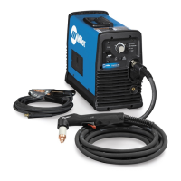
What to do if the Miller Electric Welding System temperature trouble light is on?
- CCynthia SmithJul 29, 2025
If the temperature trouble light is on, it indicates that the inverter heat sink or output heat sink is overheating. Allow the fan to run, and the trouble light should go out once the unit has cooled down. If the problem persists, have a Factory Authorized Service Agent check the control board.