Do you have a question about the Miller Electric SYNCROWAVE 250 and is the answer not in the manual?
Explains symbols indicating possible hazards in procedures.
Details potential electric shock, burn, and injury hazards during servicing.
Discusses low-frequency electric and magnetic fields and their effects.
Explains hazard symbols and their meanings on the unit.
Details the information found on the CE rating label.
Provides a comprehensive list of symbols used in the manual and their meanings.
Lists technical specifications of the welding power source.
Shows voltage and amperage output capabilities for DC and AC modes.
Explains duty cycle percentages and overheating protection measures.
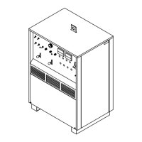
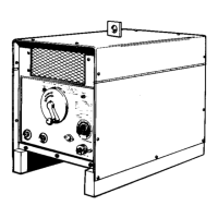
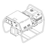
Guides on choosing a suitable location for the welding unit, considering airflow.
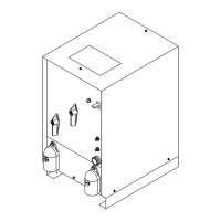
Provides physical dimensions and weight specifications of the unit.
Advises on safe handling and movement to prevent tipping hazards.
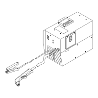
Details weld output connections and guidance on selecting appropriate cable sizes.
Describes the function and pinout of the Remote 14 receptacle.
Explains the 115V AC receptacle and shielding gas connection setup.
Provides recommendations for input voltage, amperage, and conductor sizing.
Instructions on setting jumper links and connecting input power for correct voltage.
Identifies and describes the function of each control on the front panel.
Explains how to use the output selector for DCEN, AC, and DCEP modes.
Describes the Ammeter and Voltmeter functions and readings.
Details the controls for reducing current at the end of a weld cycle.
Explains the controls for setting duration for spot welding operations.
Describes how the AC balance control affects cleaning and penetration.
Explains how to adjust and set the welding amperage.
Details the switch for selecting unit output control method.
Explains how arc control (dig) affects welding characteristics.
Describes setting the duration for gas flow after welding stops.
Explains the high frequency start and continuous modes.
Details setting gas flow duration before arc initiation.
Lists common troubles and their recommended remedies.
Provides a circuit diagram for troubleshooting power source issues.
Displays waveforms related to troubleshooting circuit diagrams.
Provides guidance for testing the control board PC1.
Lists voltage readings and test points for control board PC1.
Offers testing information for the remote board PC2.
Lists test point values for the remote 14 filter board PC2.
Instructions for calibrating the unit's ammeter and voltmeter.
Diagrams showing input voltage labels and connection points.
Outlines recommended maintenance tasks and schedules.
Describes the function and reset procedure for circuit breaker CB1.
Details the location and function of fuses F1 and F2.
Provides instructions for adjusting the spark gap settings.
Explains the use of HF in GTAW and SAW welding processes.
Identifies sources of HF radiation and potential interference issues.
Provides guidelines for proper installation to minimize HF interference.
Lists parts for the main assembly of the Syncrowave 250.
Lists components for the front panel assembly.
Lists parts for the Si diode rectifier assembly.
Lists components for the rear panel assembly.
Lists components for the mounting panel.
Lists parts for the lower front control panel.
Lists parts for optional equipment available for the unit.
| Input Frequency | 60 Hz |
|---|---|
| Welding Processes | TIG, Stick |
| TIG Welding Capability | Yes |
| Stick Welding Capability | Yes |
| High Frequency Start | Yes |
| Pulse Welding | Yes |
| Input Voltage | 208/230/460 V |
| Input Phase | 1 or 3 |
| Output Voltage Range | 10 - 30 V |
| Rated Output | 250 A at 30 V |
| Duty Cycle | 60% |
| AC/DC Output | AC/DC |