Do you have a question about the Miller Electric S-21E and is the answer not in the manual?
Details critical safety warnings like electric shock, arc rays, fumes, and moving parts.
Procedure for installing and selecting the correct drive rolls for wire feeding.
Steps to connect the welding gun, shielding gas, and 14-pin plug.
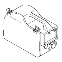
Guidance on installing wire spools and threading wire through the feeder.
Instructions for initiating and testing wire feed operation.
Detailed explanation of how the wire feeder functions.
Systematic approach to diagnosing common wire feeder issues.
Specific voltage checks for PC1 and PC2 boards.
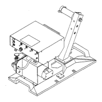
List of parts for the main assembly of the wire feeder.
| Input Frequency | 50/60 Hz |
|---|---|
| Output Current Range | 30-90A |
| Wire Size Capacity | 0.023 - 0.045 in (0.6 - 1.2 mm) |
| Wire Feed Speed | 50-450 ipm |
| Input Phase | Single Phase |