EasyManua.ls Logo

Miller Gold Seal Model 420 User Manual

Miller Gold Seal Model 420
20 pages
To Next Page IconTo Next Page
Page #1 background imageLoading...
Page #1 background image
cover 7/93 – ST-155 507-A PRINTED IN USA
1997 MILLER Electric Mfg. Co.
Read and follow these instructions and all
safety blocks carefully.
Have only trained and qualified persons
install, operate, or service this unit.
Call your distributor if you do not understand
the directions.
Give this manual to the operator.
For help, call your distributor
or: MILLER ELECTRIC Mfg. Co., P.O. Box
1079, Appleton, WI 54912 414-734-9821
OWNER’S
MANUAL
October 1997 Form: OM-174 470B
Effective With Serial No. KH531011
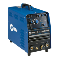
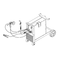
Gold Seal Model 420
CV/DC Welding Power Source/Wire Feeder
For FCAW And GMAW Welding
90 Amperes, 18 Volts At 20% Duty Cycle
Uses 115 Volts AC, Single-Phase Input Power
Overheating, Short-Circuit, And Motor Overload Protection
Usable Range Of 30 To 130 Amperes
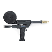
Includes Gun, Welding Wire, And Gas Valve

Questions and Answers:

Miller Gold Seal Model 420 Specifications

General IconGeneral
BrandMiller
ModelGold Seal Model 420
CategoryWelding System
LanguageEnglish

Summary

Section 1 - Specifications

1-1. Volt-Ampere Curve And Duty Cycle Chart

Provides charts detailing the voltage-amperage characteristics and operational duty cycles of the welding unit.

Section 2 - Installation

2-1. Installing Work Clamp

Details the procedure for correctly attaching the work clamp to the workpiece for proper electrical grounding.

2-2. Installing Gas Supply

Explains how to connect the shielding gas cylinder, regulator, and flowmeter to the welding unit.

2-3. Connecting Input Power

Instructions for connecting the welding unit to a suitable and properly grounded electrical power source.

2-4. Gun Polarity For Wire Type

Guides on setting the correct polarity for different wire types and welding processes (GMAW/FCAW).

2-5. Installing Welding Gun

Step-by-step instructions for physically connecting the welding gun to the welding power source.

2-6. Threading And Feeding Welding Wire

Covers the process of loading and properly feeding the welding wire through the machine and gun assembly.

Section 4 - Maintenance & Troubleshooting

4-1. Overload Protection

Explains the unit's overload protection mechanisms, including overheating shutdowns and motor fuse F1.

4-2. Drive Assembly Maintenance

Provides guidance on maintaining the wire drive rolls, guides, and bearings for optimal wire feeding performance.

4-3. Gun Maintenance

Details routine maintenance procedures for the welding gun, including cleaning and liner replacement.

4-4. Troubleshooting

Offers solutions for common welding output and wire feeding problems encountered during operation.

Related product manuals