. A complete Parts List is available at www.MillerWelds.com
OM-283935 Page 20
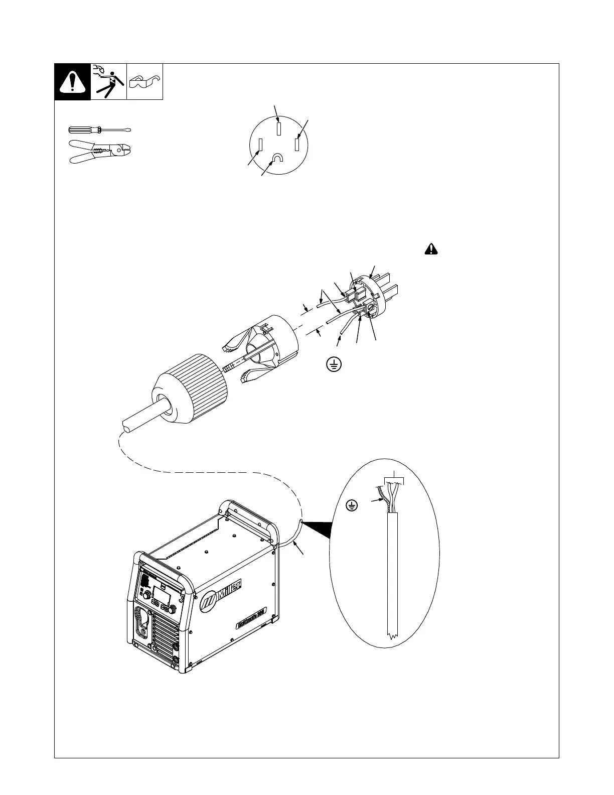
5-4. Wiring Optional 240 Volt Plug (119172) For Connection To Miller Welder/Generator
With Split-Phase 240 Volt Auxiliary Power
Ref. 120 813-D / 907780
1 Input And Grounding
Conductors
2 Plug Wired for 240 V, 2-Wire
Load
3 Neutral (Brass) Terminal And
Prong (Not Used)
4 Load 1 (Brass)Terminal And
Prong
5 Load 2 (Brass) Terminal And
Prong
6 Ground (Brass) Terminal And
Prong
7 Black And White Input
Conductors
8 Green Or Green/Yellow
Ground Conductor
! Always connect green or
green/yellow wire to ground
terminal, never to a load
terminal. Connect black (L1)
and white (L2) wires to load
terminals.
Tools Needed:
7
Green Or
Green/Yel-
low
2
3
4
5
6
240V
8
8
7
6
5
4
3 (Not Used)
Plug Front
View
1