EasyManua.ls Logo

Miller Migmatic 175 - User Manual

Miller Migmatic 175
32 pages
Print Icon
To Next Page IconTo Next Page
Loading...
Processes
Description
MIG (GMAW) Welding
Flux Cored (FCAW) Welding
Arc Welding Power Source and
Wire Feeder
Migmatic 175
CE
OM-259 158C 2015-06
OWNER’S MANUAL
Visit our website at
www.MillerWelds.com

Questions and Answers

  • S
    Sean VillaAug 2, 2025
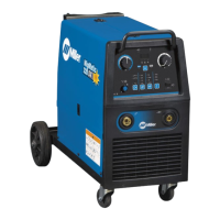
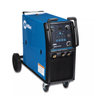
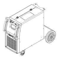
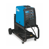
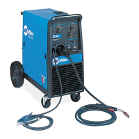
    What to do if my Miller Migmatic 175 Welding System produces a poor weld bead or the welding wire is noodle welding?
    • J
      Jason WeeksAug 2, 2025
      If your Miller Welding System produces a poor weld bead or the welding wire is noodle welding, check the polarity setting for the type of welding wire being used.
  • A
    Alex AlvaradoAug 8, 2025
    How to fix low weld output on my Miller Migmatic 175?
    • A
      Amber HoustonAug 8, 2025
      To fix low weld output on your Miller Welding System, connect the unit to the proper input voltage or check for low line voltage.
  • C
    Christina HartAug 13, 2025
    What to do if my Miller Migmatic 175 Welding System has no weld output and the wire isn't feeding?
    • K
      Kayla YoungAug 13, 2025
      If your Miller Welding System isn't producing a weld and the wire isn't feeding, ensure the line disconnect switch is On. Also, check and replace the building line fuse or reset the circuit breaker if it's open. Secure the gun trigger connections and check and replace the power switch if necessary.
  • H
    Herbert JohnsonAug 19, 2025
    How to troubleshoot no wire feed on my Miller Migmatic 175?
    • A
      Alexandra SandovalAug 20, 2025
      To troubleshoot a lack of wire feed on your Miller Welding System, first, turn the Wire Speed control to a higher setting. Then, clear any obstruction in the gun contact tip or liner and readjust the drive roll pressure. Change to the correct size drive rolls and check the gun trigger and leads, repairing or replacing the gun if necessary. If the issue persists, have a Factory Authorized Service Agent check the main control board.
  • W
    William DominguezAug 26, 2025
    Why is the overload light on and there is no weld output on my Miller Migmatic 175 Welding System?
    • M
      Michelle AriasAug 26, 2025
      If the overload light is on and there's no weld output on your Miller Welding System, it could be due to thermostat TP1 being open (overheating). Allow the fan to run so the thermostat will close when the unit has cooled. Additionally, an overload condition might have occurred, so release the gun trigger.

Summary

From Miller to You

Declaration of Conformity

Section 1 - Safety Precautions

Symbol Usage

Explains the meaning of symbols used in the manual for hazard identification.

Arc Welding Hazards

Details potential dangers associated with arc welding, electric shock, and fumes.

Additional Symbols for Installation, Operation, and Maintenance

Provides additional symbols for safe installation, operation, and maintenance procedures.

California Proposition 65 Warnings

Lists chemicals known to cause birth defects or cancer in California.

Principal Safety Standards

Lists relevant safety standards and their sources for reference.

EMF Information

Information on electromagnetic fields and their potential impact on medical devices.

Section 2 - Definitions

Additional Safety Symbols and Definitions

Defines additional safety symbols specific to CE products.

Miscellaneous Symbols and Definitions

Explains various technical and operational symbols used in the manual.

Section 3 - Specifications

Serial Number and Rating Label Location

Describes where to find the serial number and rating information on the product.

General Specifications

Provides detailed technical specifications of the welding machine.

Environmental Specifications

Outlines IP rating, operating, and storage temperature ranges.

Duty Cycle and Overheating

Explains duty cycle limitations and procedures for handling overheating.

Volt-Ampere Curves

Displays normal and overload volt-ampere characteristics of the unit.

Section 4 - Installation

Selecting A Location

Guidelines for choosing a suitable installation location for the equipment.

Installing Gas Supply

Step-by-step instructions for connecting the gas cylinder and regulator.

Drive Rolls and Wire Guide Setup

Procedures for changing, aligning drive rolls and wire guides for optimal performance.

Threading Welding Wire and Adjusting Pressure Roll Tension

Detailed steps for threading wire and setting drive roll pressure.

Electrical Service Guide

Recommendations for appropriate electrical service for the unit.

Connecting 1-Phase Input Power For 230 VAC

Guide for connecting the welding machine to a 230 VAC power source.

Section 5 - Operation

Controls Overview

Identifies and describes the functions of the machine's controls and indicators.

Section 6 - Maintenance and Troubleshooting

Unit Overload

Explains the unit overload condition and how to reset it.

Troubleshooting Common Issues

Provides solutions for common problems encountered with the equipment.

Section 7 - Electrical Diagram

Section 8 - Parts List

Warranty Information

Limited Warranty Terms and Conditions

Details the terms, conditions, and duration of the Miller limited warranty.

Service and Records

Owners Record

Section for users to record personal ownership and service details.

Contacting Distributor or Service Agency

Information on how to contact distributors or service agencies for support.

Miller Migmatic 175 Specifications

General IconGeneral
BrandMiller
ModelMigmatic 175
CategoryWelding System
LanguageEnglish

Related product manuals