C
Courtney PerkinsAug 4, 2025
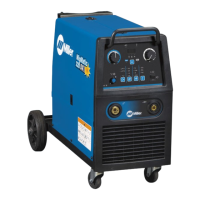
How to fix Miller MIGMATIC 250 Welding System when there is no weld output and wire does not feed?
- KKevin TerryAug 4, 2025
If your Miller Welding System isn't producing a weld and the wire isn't feeding, first ensure the line disconnect switch is On, replace the building line fuse or reset the circuit breaker if open, and reset circuit breaker CB1. Also, secure the gun trigger connections and check the continuity of the power switch S1, replacing it if needed. For further assistance, have a Factory Authorized Service Agent check the main transformer T1, thermostats TP1 and TP2, and the main control board PC1 and their connections, replacing them if necessary.