Do you have a question about the Miller SuitCase 8RC and is the answer not in the manual?
Explains symbols indicating hazardous situations and their meaning.
Details potential dangers associated with arc welding processes and precautions.
Covers specific safety symbols for setup, use, and upkeep of equipment.
Alerts users to chemicals in products that may cause birth defects or cancer.
Lists key safety standards and sources for further information.
Provides guidance on electromagnetic fields and their potential impact on medical implants.
Explains symbols specific to CE products and general safety warnings.
Defines various symbols used in the manual for controls, processes, and parameters.
Guides users to find product identification and input power details.
Addresses electromagnetic field and compatibility information for CE marked products.
Lists technical specifications including input power, wire feed, and dimensions.
Details environmental ratings like IP rating and suitability for outdoor use.
Explains the function of each pin on the 14-pin connector.
Recommends specific welding guns for different welding processes.
Visually illustrates how to connect the wire feeder to the power source and other components.
Provides step-by-step instructions for installing and adjusting wire feeding components.
Details the procedure for connecting the welding gun to the wire feeder.
Explains how to connect the shielding gas supply to the wire feeder.
Guides the user on how to connect the weld cable to the equipment.
Offers a chart to determine the correct weld cable size based on amperage and length.
Provides instructions for loading and setting up welding wire in the feeder.
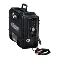
Identifies and explains the function of the wire feeder's main controls.
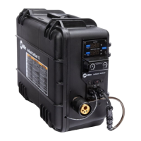
Details the operation of the optional meter display and its controls.
Explains how to configure the digital meter via DIP switches for different displays.
Lists replacement parts and consumables for various welding guns.
Outlines regular maintenance tasks and schedules for the equipment.
Explains the built-in protection mechanisms against overload and overheating.
Provides instructions for cleaning the shielding gas filter fitting.
Offers solutions for common problems encountered with the wire feeder.
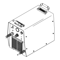
Detailed breakdown of the wire feeder's main assembly with part numbers.
Illustrates the front panel components when meters are not installed.
Shows the front panel components when meters are included.
Lists drive roll and wire guide kit options based on wire diameter and type.
| Duty Cycle | 60% at 200A |
|---|---|
| Input Phase | 1 |
| Output Type | DC |
| Processes | MIG |
| Wire Size | .030 - .045 in |
| Wire Feed Speed | 50-700 IPM |
| Wire Feed Speed Range | 50-700 IPM |