CHEMICAL INLET VALVES
1/2" Stainless steel
1/2" PVC
VALVE
24 USGPM (H2O @ 15 PSI)
30 USGPM (H2O @ 15 PSI)
FLOW RATE
The approximate full-open flow rate of this chemcial inlet valve is shown
above. At lower pressure, the flow will be reduced approximately as the
square root of the ratio obtained by dividing the actual applied pressure by
15 PSI (1ATU).
The calibrating valve can vary the flow from full-open to about 25 % of
full-open. See TABLE 1 and FIGURE 1 below for description of valve
positioning. Never use this calibrate valve to reduce the flow to less than
25% because the resultant flow will not be consistent.
Should 25% of full-flow be too great, reduce the amount of chemicals
actually injected by (1) reducing the chemical pressure, or (2) reducing the
stock chemical concentration (increasing the dilution), or (3) reducing the
time the chemical valve is commanded by the SITMIL to remain open.
(However, the valve should never be commanded to open less than about
10 seconds, because the opening and closing time of the chemical inlet
valve would become a large percentage of the injection time and thus cause
certain variations in the amount of chemical actually injected).
FIGURE 1
O
=90
O
=76
O
=62
O
=47
FLOW
VALVE
POSITIONING
REF.
25% 47
50% 62
75% 76
FULL 90
O
O
O
O
TABLE 1
ÎFIGURE 19
(MSIN0201BE)
Î Central Liquid Supply Systems
WATER CONNECTION FOR:
AUTOMATIC SUPPLY INJECTOR
AND BALANCING VALVES (If
machine is so equipped).
USE HOT WATER IF IT IS AVAILABLE.
SET PRESSURE REGULATOR FOR
28 PSI WHEN THERE IS NO FLOW
OF FLUSHING OR BALANCING WATER.
ÎFIGURE 20
(MSIN0201BE)
ÎDivided Cylinder, 52" and 72"
Open Pocket Non-Tilt Machines
NOTE: CALIBRATE SUPPLIES
#1 AND #2 TWICE.
SUPPLIES #1 AND #2 HAVE TWO FLOW
RATES: NORMAL RATE FOR TIMES
A. A1, B, AND B1; HIGH RATE FOR C
AND C1. CALIBRATE BOTH #1 AND #2
AT TIME A OR B AND AT TIME C.
ÎFIGURE 21
(MSIN0201BE)
ÎCalibrating Liquid
Supply Manifold
ÎFIGURE 22
(MSIN0201BE)
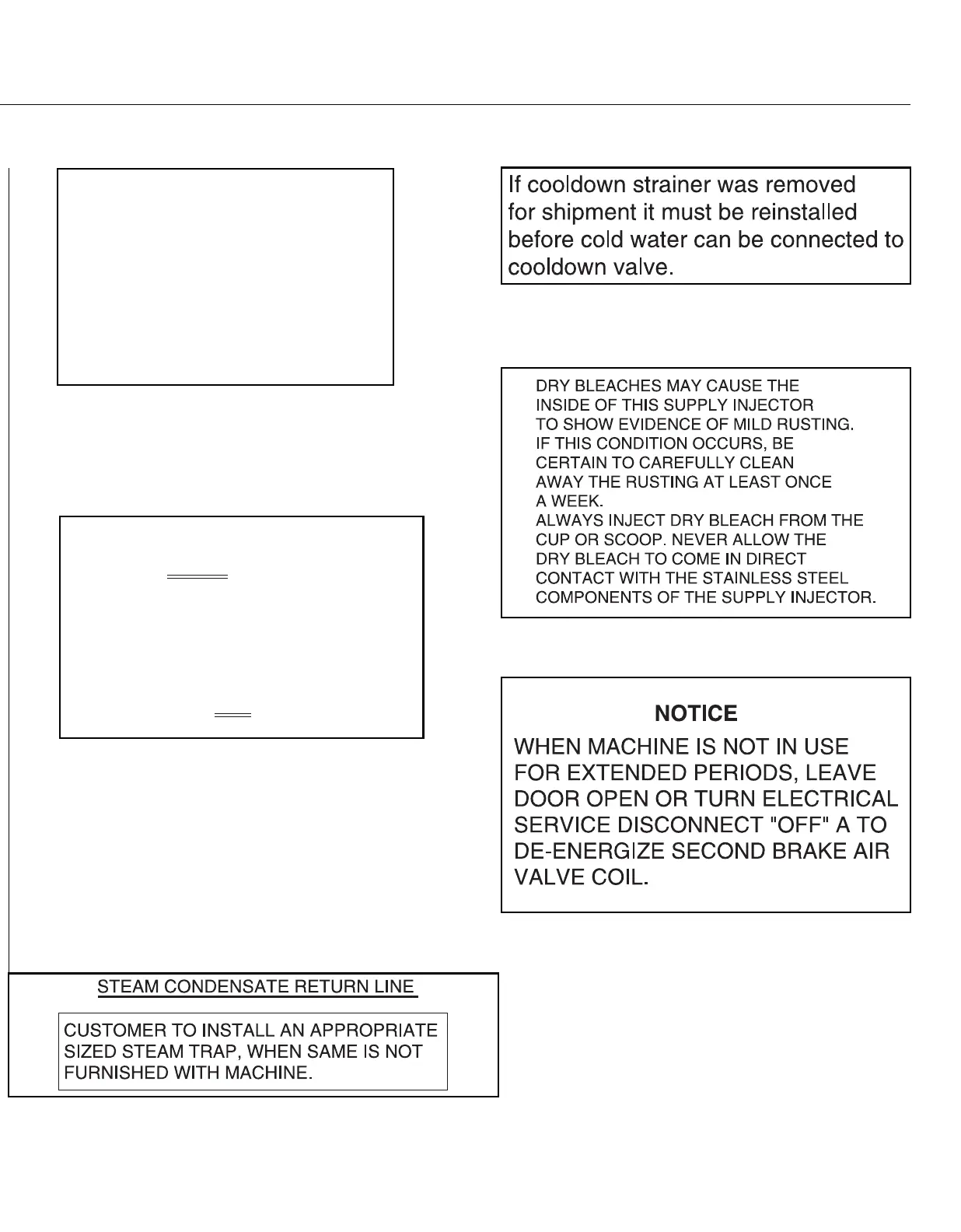
ÎCooldown/Spraydown Machines
(If applicable)
ÎFIGURE 23
(MSIN0201BE)
ÎBleach Precaution
ÎFIGURE 24
(MSIN0201BE)
ÎDoor Precaution
ÎFIGURE 25
(MSIN0201BE)
ÎIndirect Steam Condensate Return
45