How to Use Milnor
®
Electrical Schematic Diagrams
PELLERIN MILNOR CORPORATION
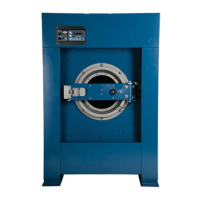
Figure 15: Mechanical Switch (SM) Figure 16: Pressure Switch (SP)
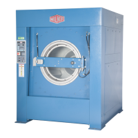
ST=Switch, Temperature Operated (Figure 17)—A switch that is actuated at a preset
temperature (e.g., dryer safety probes) or has adjustable set points (e.g., Motometers or
Combistats).
TB=Terminal Board (Figure 18)—A strip or block for attaching or terminating wires.
Figure 17: Temperature Switch
(ST)
Figure 18: Terminal Board (TB)
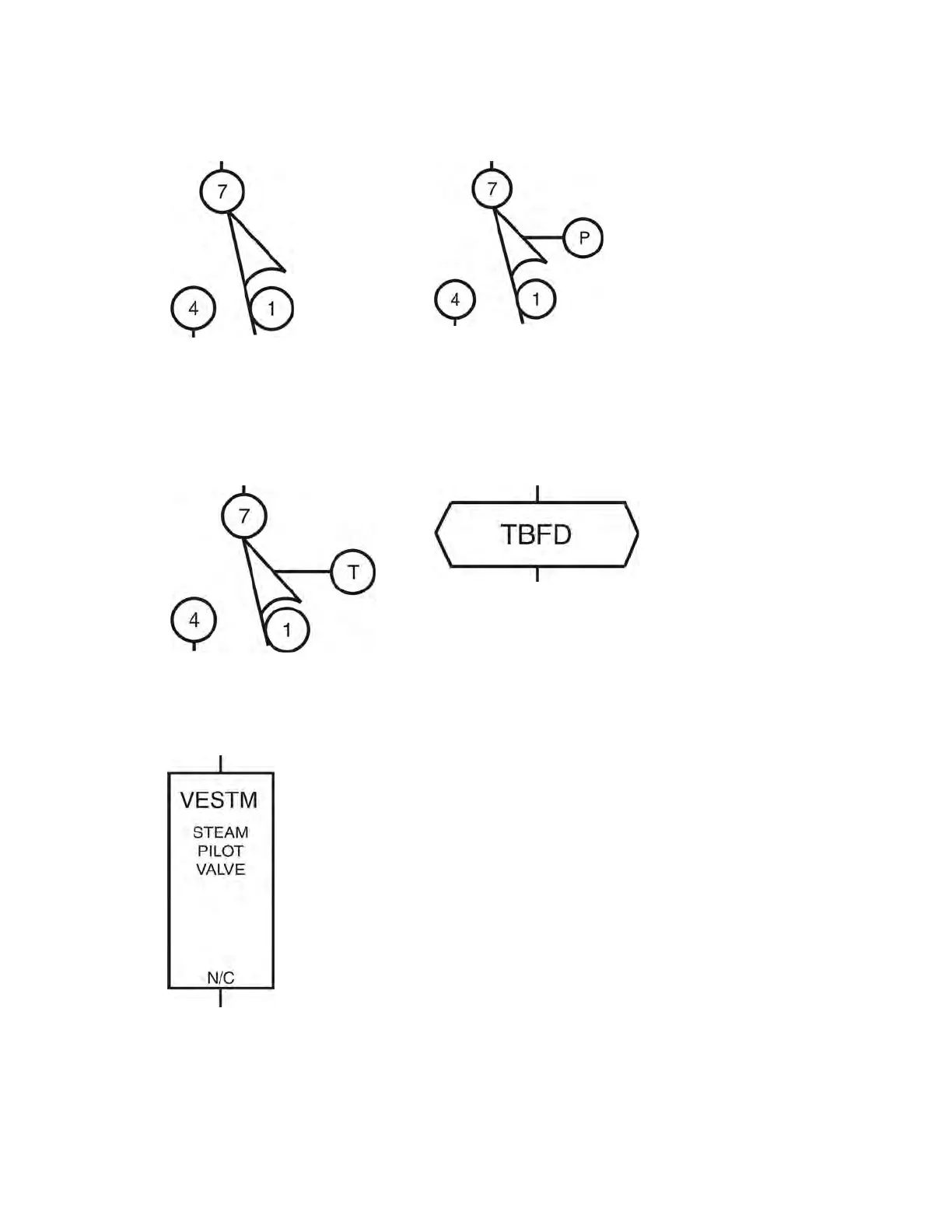
VE=Valve, Electric Operated (Figure 19)—A valve operated by an electric coil to control the
flow of fluid. The fluid can be air, water or hydraulic.
Figure 19: Electrically Operated
Valve (VE)
ZF=Rectifier (Figure 20)—A solid state device that converts alternating current to direct
current.
16

 Loading...