How to Use Milnor
®
Electrical Schematic Diagrams
PELLERIN MILNOR CORPORATION
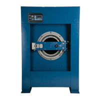
Figure 20: Bridge Rectifier (ZF)
Component Symbol Legend
.
A. Alternating current input
B. Direct current output
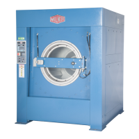
Figure 21: Bridge Rectifier
Component Legend
.
A. Alternating current in
B. Negative direct current
out
C. Positive direct current out
WC=Wiring Connector—A coupling device for joining two cables or connecting a cable to an
electronic circuit or piece of equipment. Connectors are male or female, according to whether
they plug into or receive the mating connector.
2. Component Terminal Numbering
CAUTION 1 : Risk of Mis-wiring—Due to electrical component manufacturing
inconsistencies, the pin numbers imprinted on components such as connectors and relay bases
used on Milnor machines often do not correspond to the pin numbers shown in the schematics.
• Ignore pin numbers imprinted on in-line connectors (e.g., Molex connectors) and relay
bases.
• Use the pin identification illustrations herein to identify pins on these components.
17

 Loading...