www.milorange.com
2. Loosen the ball joint on the clamp, aim the TAC camera at the area where the trainee will be during
training then tighten the ball joint to secure the camera’s position.
3. Connect the power supply to the TAC camera and to an AC power outlet.
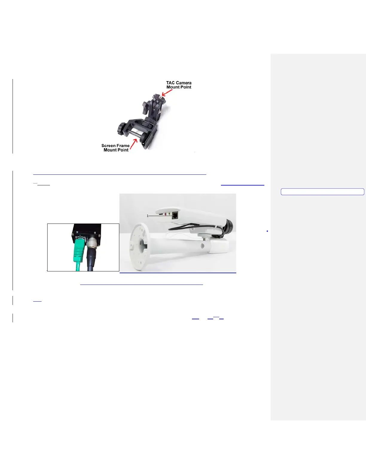
4.3. Connect the supplied network cable to the network port on the TAC camera. (Figure 13, Item 1)
Figure 13 – TAC Camera with supplied mounting hardware
4. Run the network cable from the TAC camera to the Hit Detect & Flashlight camera box, avoiding
the area where the trainee will be during training. Connect the network cable from the TAC Camera
to the AUX port on the Hit Detect & Flashlight camera box. (Figure 14, Item m)1)
Formatted: PICTURE, Left